IEEE-488 Reference
3-17
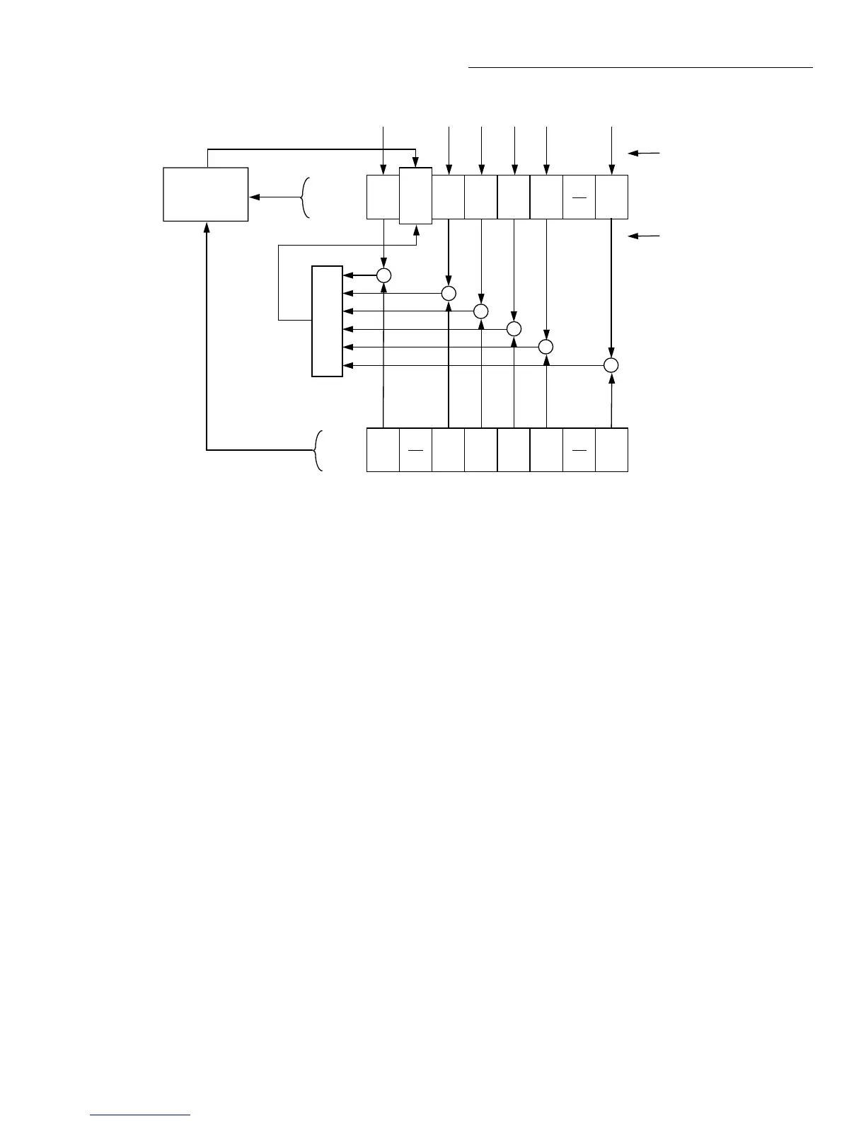
Service Request Enable Register — This register is pro-
grammed by the user and serves as a mask for the Status
Summary Message bits (B0, B2, B3, B4, B5 and B7) of the
Status Byte Register. When masked, a set summary bit in the
Status Byte Register cannot set bit B6 (MSS/RQS) of the
Status Byte Register. Conversely, when unmasked, a set
summary bit in the Status Byte Register sets bit B6.
A Status Summary Message bit in the Status Byte Register is
masked when the corresponding bit in the Service Request
Enable Register is cleared (0). When the masked summary
bit in the Status Byte Register sets, it is ANDed with the cor-
Figure 3-12
Status byte and service request (SRQ)
Status Summary Messages
* STB?
Serial Poll
OSB
(B7)
RQS
(B6)
MSS
ESB
(B5)
MAV
(B4)
QSB
(B3)
EAV
(B2) (B1) (B0)
OR
* SRE
* SRE?
Status Byte
Register
Service Request
Enable Register
OSB = Operation Summary Bit
MSS = Master Summary Status
RQS = Request for Service
ESB = Event Summary Bit
MAV = Message Available
QSB = Questionable Summary Bit
EAV = Error Available
MSB = Measurement Summary Bit
& = Logical AND
OR = Logical OR
OSB
(B7) (B6)
ESB
(B5)
MAV
(B4)
QSB
(B3)
EAV
(B2) (B1) (B0)
&
&
&
&
&
MSB
MSB
&
Service
Request
Generation
Read by Serial Poll
Read by *STB?
responding cleared bit in the Service Request Enable Regis-
ter. The logic “0” output of the AND gate is applied to the
input of the OR gate and thus, will not set the MSS/RQS bit
in the Status Byte Register.
A Status Summary Message bit in the Status Byte Register is
unmasked when the corresponding bit in the Service Request
Enable Register is set (1). When the unmasked summary bit
in the Status Byte Register sets, it is ANDed with the corre-
sponding set bit in the Service Request Enable Register. The
logic “1” output of the AND gate is applied to the input of
the OR gate and thus, sets the MSS/RQS bit in the Status
Byte Register.