Keysight B1505A User’s Guide, Edition 12 3-11
Accessories
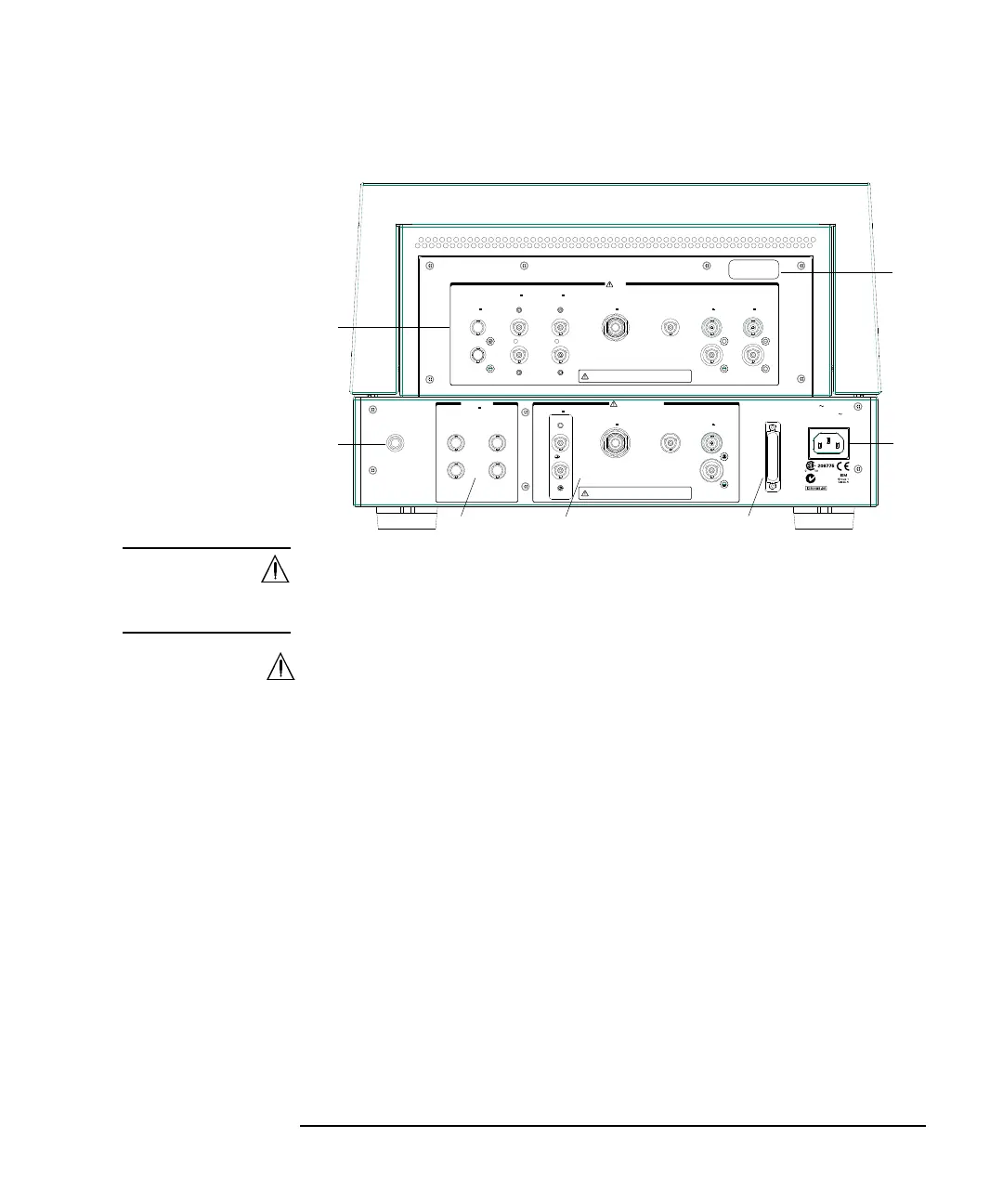
Rear Panel
WARNING The connector cap must be connected to the unused input connectors for safety.
Le capuchon du connecteur doit être raccordé aux connecteurs d'entrée
inutilisés.
1. Input
• AUX1 and AUX2 input connectors
BNC connectors. For connecting MFCMU or external instruments.
• HPSMU1 and HPSMU2 input connectors
Force and Sense triaxial connectors. For connecting 16493K Kelvin triaxial
cable or 16494A triaxial cable from the HP/MPSMU.
• HVSMU1 input connector
HV(jack) connector. For connecting 16493T HVSMU cable from the
HVSMU or the HVMCU High.
• GNDU1 input connector
GNDU triaxial connector. For connecting 16493L GNDU cable from the
GNDU or the HVMCU Low.
N10149
Interlock
HPSMU3
±200 V Max
HVSMU2
±3 kV Max
GNDU2
Module Selector Input
Force
Sense
HVSMU1
±3 kV Max
GNDU1
Force
Sense
Force
Sense
Force
Sense
Force
Sense
Force
Sense
±25 V Max
HpotH cur
LpotLcur
Digital I/O
LINE
100– 240 V
50/60 Hz
35 VA Max
MF CMU Input
Input
To avoid electrical shock and instrument damage,
do not remove the short cap and cables during operation.
To avoid electrical shock and instrument damage,
do not remove the short cap and cables during operation.
HPSMU1
±200 V Max
HPSMU2
±200 V Max
HCSMU1
±40 V Max
AUX
±200 V Max
HCSMU2
±40 V Max
HCSMU3
±40 V Max
1
2
5
4
3
1
2
6
7