3-20 Keysight B1505A User’s Guide, Edition 12
Accessories
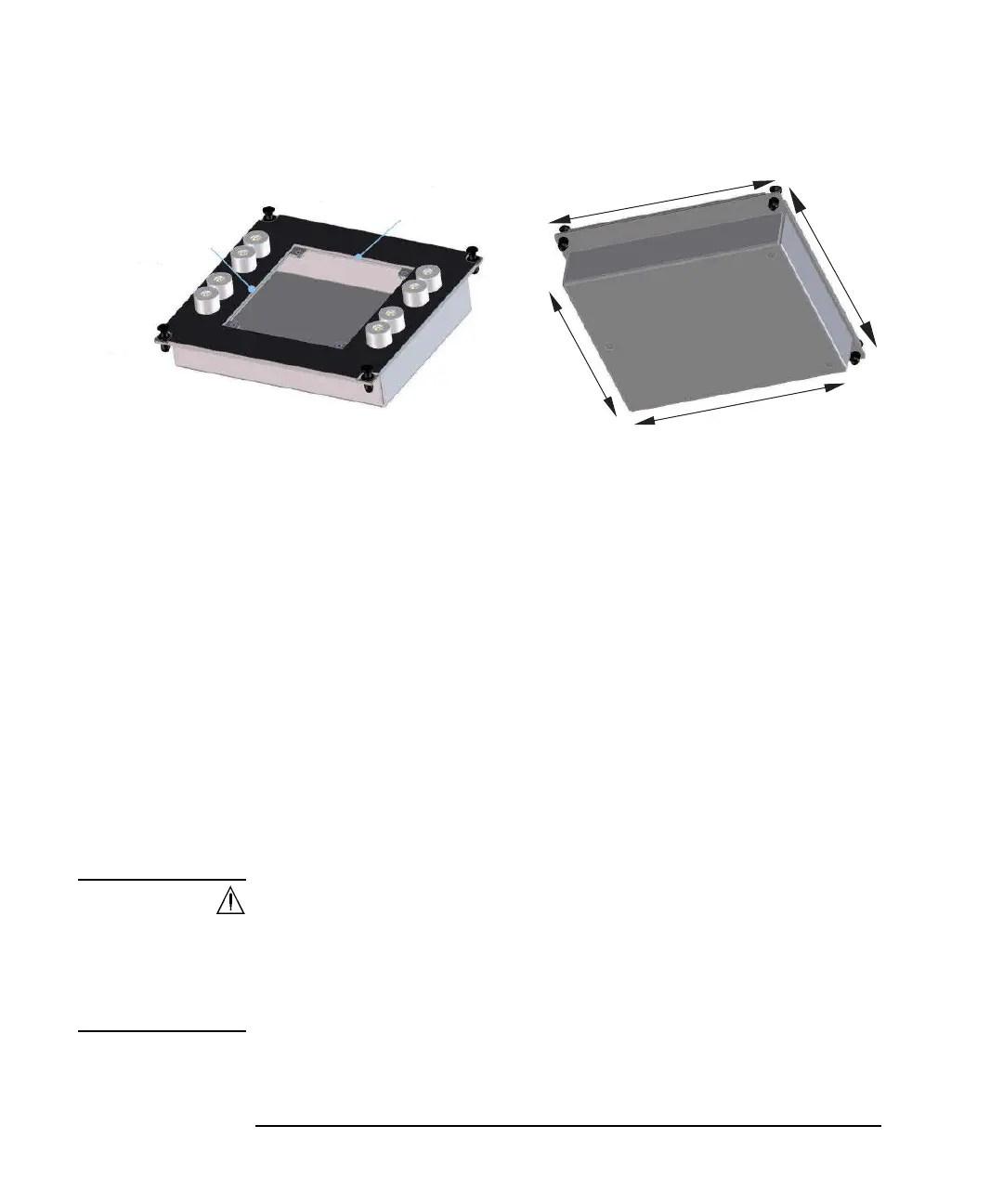
Figure 3-4 Universal Socket Module
a. Prepare the following parts.
• blank board suitable for mounting the socket or packaged device
• screw M3, 4 ea., for fixing the blank board on the socket module
• wire, adequate length and quantity, for making connections
• hexlobe (torx type) screwdriver T-10
• socket, if you use, and packaged device under test (DUT)
b. Cut the blank board in 104 mm 89 mm square.
c. Make four screw holes on the board. The holes should be 4.5 mm inside
from the edge.
d. Fix the board to the blank module.
e. Remove the cover bottom of the blank module.
f. Mount the socket or DUT on the board and solder wire between its terminals
and the blank module terminals 1 to 8.
WARNING Make enough space between the socket/DUT terminal and the shield/chassis,
for example, about 1 mm for maximum 200 V output and 6 mm for 3000 V, to
prevent discharge and any accident.
Laissez suffisamment d'espace entre la prise/la borne MST et la protection/le
châssis. Par exemple, environ 1 mm pour une sortie de 200 V au maximum et 6
mm pour 3 000 V afin d'éviter toute décharge et tout accident.
g. Reattach the cover.
90 mm
(Nut pitch: 95 mm)
165 mm
165 mm
129 mm
160 mm
105 mm
Height: 34 mm (45 mm including terminal)
(Nut pitch: 80 mm)
2
1
3
4
5
6
7
8