Keysight B1505A User’s Guide, Edition 12 3-23
Accessories
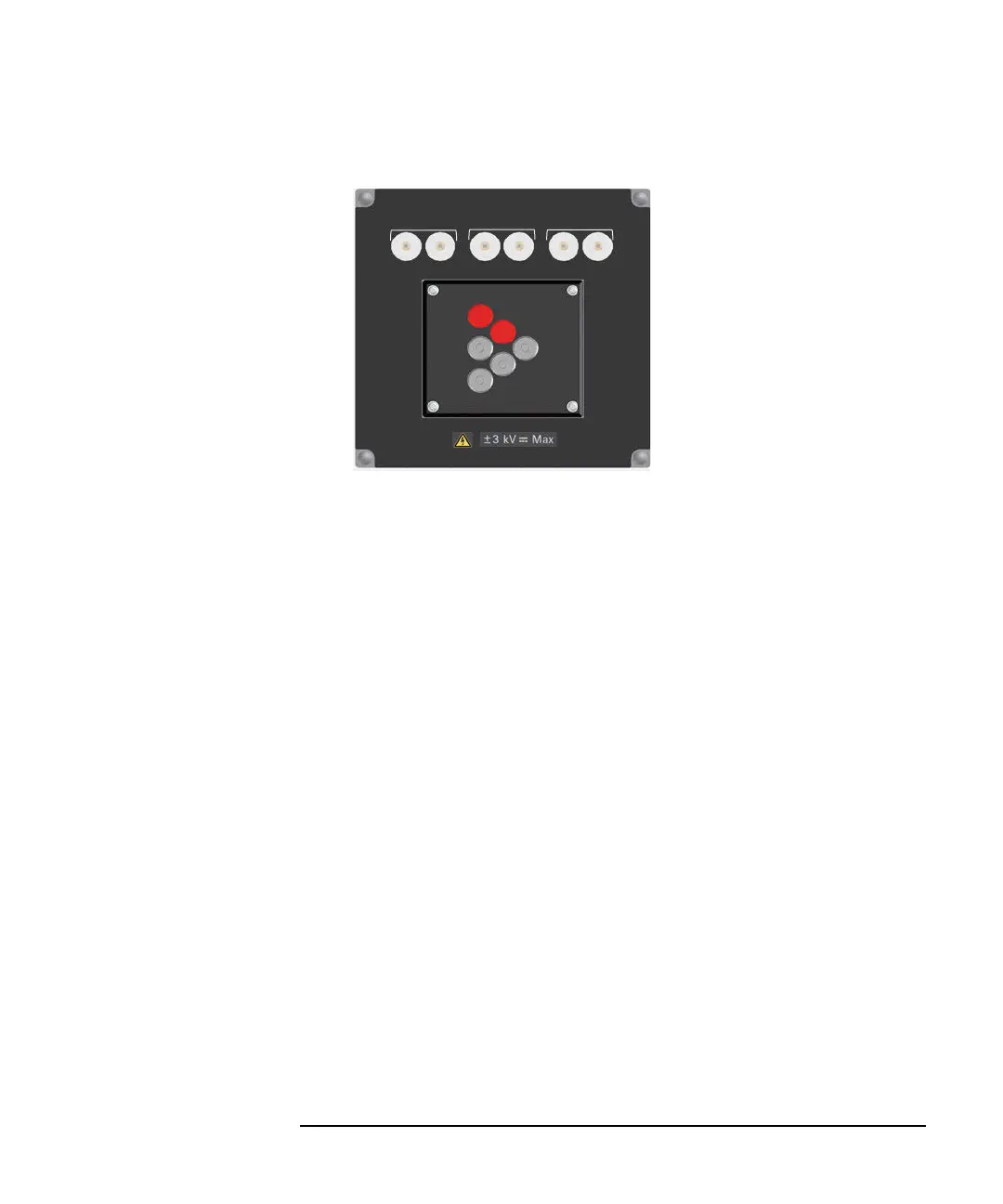
Figure 3-6 Curve Tracer Test Adapter Socket Module
8. Gate charge socket module (N1259A-014)
This socket adapter is designed for performing the gate charge measurement.
To use this module, see the following simple instruction.
a. Attach the socket module to the test fixture.
b. Connect wires between the socket module terminals and the fixture output
terminals. You can use the following wires supplied with the socket module.
• N1254A-508: long wire (red), 4 ea.
• N1254A-509: long wire (black), 4 ea.
• N1265-61751: short wire (red), 2 ea.
• N1265-61752: short wire (black), 2 ea.
For making the Kelvin connection, Force and Sense must be connected
together at the device terminal.
Figure 3-8 and Figure 3-9 show connection examples.
c. Set the current control device on the left socket or connect the load resistor
between the studs for the resistor.
The current control device must be an extra 3-pin inline package device
which is expected to have the same characteristics as DUT. If the device is
not available, use a load resistor. The resistor must satisfy the following
specifications.
Resistance = Vr/Ir (Vr: rated voltage, Ir: rated current)
Collector / Drain
Emier / Source Base / Gate
N1259A Opt 013
Force Sense
Force Sense
Force Sense
Curve Tracer Test Adapter Socket
1
2
5
6
4
3
Internal connection
1: Collector/Drain Force
2: Collector/Drain Sense
3: Emitter/Source Force
4: Emitter/Source Sense
5: Base/Gate Force
6: Base/Gate Sense
A
BC
Maximum voltage: 3000 V
Maximum current:
A-Force: 500 A pulse, 39 A dc
A-Sense: 40 A pulse, 2 A dc
B-Force: 500 A pulse, 39 A dc
B-Sense: 40 A pulse, 2 A dc
C-Force: 40 A pulse, 2 A dc
C-Sense: 40 A pulse, 2 A dc