3-24 Keysight B1505A User’s Guide, Edition 12
Accessories
Peak power Vr Ir 1 ms
d. Set your DUT on the right socket.
e. Close the fixture cover and perform measurement.
CAUTION Do not apply voltage/current over the maximum limit of the socket module.
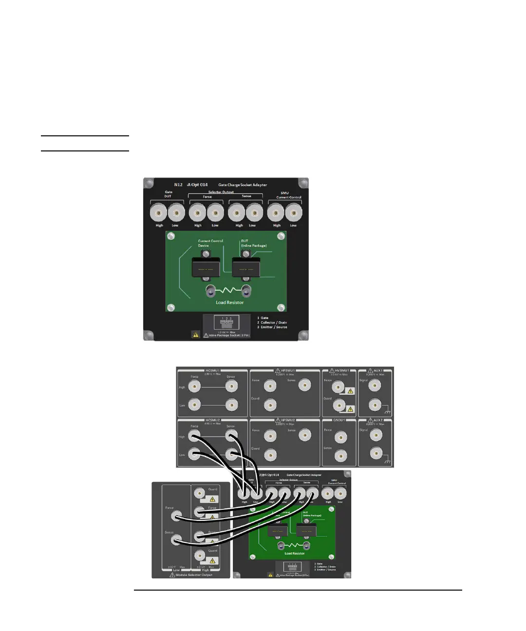
Figure 3-7 Gate Charge Socket Module
Figure 3-8 Connection Example for High Voltage Gate Charge Measurement
Collector / Drain
Emier / Source Base / Gate
N1259A Opt 013
Force Sense
Force Sense
Force Sense
Curve Tracer Test Adapter Socket
1
2
5
6
4
3
Gate DUT
High: Max. 30 V / 1 A
Low: Max. 10 V / 1 A
Selector Out Force
High: Max. 3000 V / 500 A
Low: Max. 10 V / 500 A
Selector Out Sense
High: Max. 3000 V /20 mA
Low: Max. 10 V / 20 mA
SMU Current Control
High: Max. 30 V / 1A floating 3000 V
Low: Max. 10 V / 1A floating 3000 V
A
BC
59