3-34 Keysight B1505A User’s Guide, Edition 12
Accessories
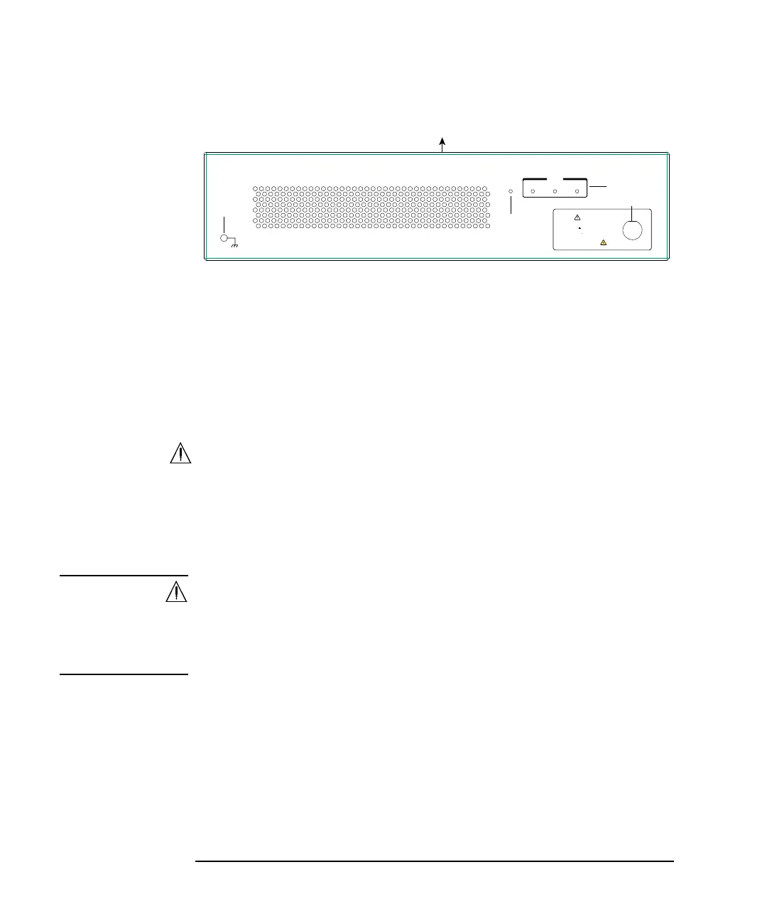
Front Panel
1. Terminal for connecting wrist strap
2. Power indicator
This LED turns yellow when the AC power is applied to the test fixture.
This LED turns green when the test fixture is ready to use.
3. Status indicator
A green LED lights to indicate the present connection path of the selector. See
Figure 3-11 and Table 3-5 for the status indicator and the connection path.
4. Hazardous voltage status indicator
This red LED lights when a measurement resource applies dangerous voltage.
This indicator is connected to the B1505A via the Interlock connector and works
with the High Voltage indicator on the B1505A’s front panel.
Warming labels written in French, German, and Japanese are furnished. Attach
the label to the front panel of the fixture if you need.
WARNING The red light indicates that hazardous voltage (maximum ± 10 kVdc) may
appear at measurement terminals. Check this indicator before accessing.
Le témoin rouge indique qu'une tension dangereuse (maximum ± 10 kV CC)
risque d'apparaître au niveau des bornes de mesure. Vérifiez cet indicateur
avant d’accéder.
5. Fixture cover
The fixture cover should be closed to avoid electrical shock by touching
measurement terminals and to prevent a device under test from external noise.
When the fixture cover is open, maximum SMU output is limited to ± 42 V and
UHVU output is disabled.
1
3
2
4
5
Power SMU
UHC HVSMU
Selector
N1265A
Ultra High Current Expander/Fixture
WARNING
The red light indicates that hazardous
voltage (±10 kV Max) may appear at
measurement terminals.
Check this indicator before accessing.
Shock Hazard