3-46 Keysight B1505A User’s Guide, Edition 12
Accessories
• Selector Output Low to DUT low (ex. Emitter/Source)
• Gate High to DUT drive (ex. Base/Gate Force)
• Gate Low to DUT low (ex. Emitter/Source Force)
HC/MC/DHCSMU via SMU 3 terminals should be connected as follows.
• SMU 3 High Force and Sense to DUT high
• SMU 3 Low Force and Sense to DUT low
• GNDU Force and Sense to DUT low
The GNDU signals will appear at the Selector Output Low terminals as
shown in Table 3-5.
3. Set the DUT on the socket.
4. Close the fixture cover and perform measurement.
CAUTION Do not apply voltage/current over the maximum limit of the socket module.
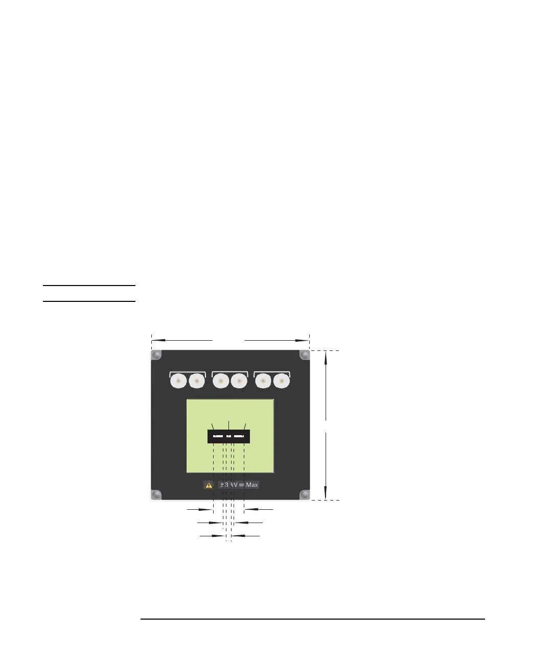
Figure 3-12 Inline Package Socket Module
Collector / Drain
Emier / Source Base / Gate
N1265A Opt 010
Inline Package Socket (3 Pin)
1
2
5
6
4
3
3
F: Force
S: Sense
1
FS
2
FS
165 mm
165 mm
3.48 mm
1.78 mm
14 mm
Height: 34 mm
(45 mm including terminal)
(58 mm including socket)
FS
13
2
Maximum current:
1-F: 500 A pulse, 39 A dc
1-S: 40 A pulse, 2 A dc
2-F: 500 A pulse, 39 A dc
2-S: 40 A pulse, 2 A dc
3-F: 500 A pulse, 39 A dc
3-S: 40 A pulse, 2 A dc
Maximum voltage: 3000 V