Keysight B1505A User’s Guide, Edition 12 3-79
Accessories
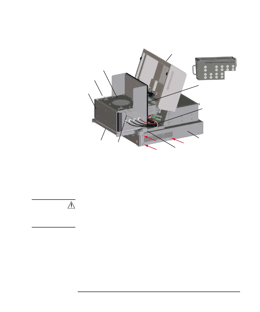
For the setup image, see the following figure.
See the following simple instruction.
1. Remove the socket module from the test fixture.
2. Install the pedestal. The N1265A fixture has three screw holes on the both sides
respectively. And, the brackets of the pedestal have the screw holes. Secure the
pedestal to the fixture using the dedicated screws supplied with this option.
WARNING For safety, firmly secure the pedestal.
Do not place other than those specified on the pedestal.
Pour des raisons de sécurité, attacher solidement le piédestal.
Ne rien placer d’autre que ce qui est spécifié sur le piédestal.
3. If you use the thermocouple, connect the thermocouple to the K Thermocouple
terminal.
4. Put the enclosure on the pedestal and connect the following cables to the
associated terminals on the fixture properly.
• Bias Tee High cable
• Bias Tee Low cable
• UHV High cable
Adapter
Pedestal
Enclosure
Enclosure
Cover
Fixture Cover
Left side wire
Right side wire
Interlock switch
under the wire head
Test Fixture
Cables for Bias Tee
and UHV