3-84 Keysight B1505A User’s Guide, Edition 12
Accessories
Front Panel
1. Power indicator
This LED turns orange when AC power is applied to the selector.
This LED turns green when the selector is ready to use.
2. IV indicator
A green LED lights to indicate when the present connection path of the selector
is in I-V measurement mode.
3. CV indicator
A green LED lights to indicate when the present connection path of the selector
is in C-V measurement mode.
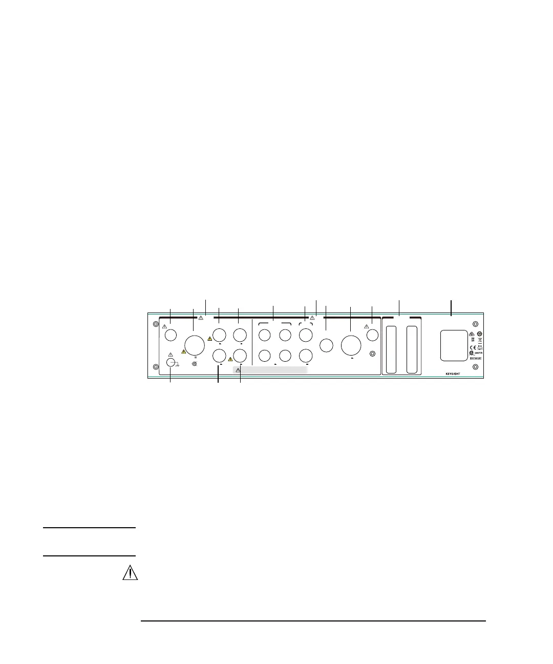
Rear Panel
1. Digital I/O connectors
Input connector: For connecting the furnished Digital I/O cable (B1506-61780)
from the Digital I/O connector of B1505A. If the selector is used with other
fixture or selector, you can also connect the output from it to this input
connector.
Output connector: For connecting the 16493G cable from the Digital I/O input
connector of the used other fixture or selector. This supports N1258A,
N1259A-300, and N1265A.
CAUTION Connect 16493G cables after turning the instruments off. Connection and
disconnection while the instruments are on may cause instrument damage.
2. Input
a. MFCMU input connectors Hcur, Hpot, Lpot, and Lcur
Force
Guard
Circuit
Common
HVSMU
To avoid electrical shock and instrument damage,
do not connect/disconnect the cables during operation.
Output Input
±3 k V Max
Lcur
Hcur
Lpot
Hpot
Force
Sense
±3 k V Max±3 k Max
±3 k
V
Max
±100 V Max
±100 V Max
±3 k
V
Max ±25 V Max ±100 V Max
~
LINE
100
-
240 V
~
50/60 Hz
70 VA Max
Input Output
Digital I/O
HVSMU
Base/Gate
MFCMU SMU
GNDU
Collector/Drain
AC/DC GuardEmitter/Source
Interlock
Interlock
MSIP-REM-ATI-
1H-B1507A
T2 T1
T3 T4
N1272
-
61001