3-102 Keysight B1505A User’s Guide, Edition 12
Accessories
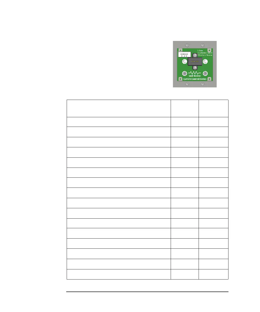
2. Mount the current control device on the
socket or the load resistor on the studs.
3. Replace and secure the small panel.
Do not perform measurement without the
panel.
Table 3-19 Connectors and Maximum Voltage/Current of N1274A
Connector Label
Maximum
Voltage
Maximum
Current
Input from N1258A
High Force
3000 V 20 A
High Sense
3000 V 200 mA
Low Force
10 V 20 A
Low Sense
10 V 20 mA
Input From B1505A
Current Control MCSMU Force
30 V 1 A
Current Control MCSMU Sense
30 V 1 A
DUT Gate Control MCSMU/HCSMU Force
30 V 1 A
DUT Gate Control MCSMU/HCSMU Sense
30 V 1 A
Output
High Force
3000 V 20 A
High Sense
3000 V 20 mA
Low Force
10 V 20 A
Low Sense
10 V 20 mA
Gate
30 V 1 A