Removing/Installing Power Modules
Refer to Power Module Installation for details.
Step 1. Remove the top (or bottom) covers. Loosen the thumbscrews to remove the covers. Turn the
unit upside-down to remove the bottom cover.
Step 2. To remove a power module, first remove the connector from the end of the module. Then
remove the two fastening screws at either end of the module. Grasp the module at the ends (near the
fan and the output connector), and lift it straight up out of the mainframe.
Equipment Damage Backplane connector pins are exposed in empty module slots.
Ensure that the pins are protected from damage whenever the covers are removed.
Step 3. To install a module, align the module over the alignment pins, and push it down onto the
backplane connector.
Step 4. Fasten the module to the mainframe. Install the two fastening screws to either end of the
module. Install the connector plug into the module.
Step 5. Install the top (or bottom) covers when finished.
Removing/Installing the Top Chassis (5002-2850)
Step 1. Remove the top cover and any modules as previously described.
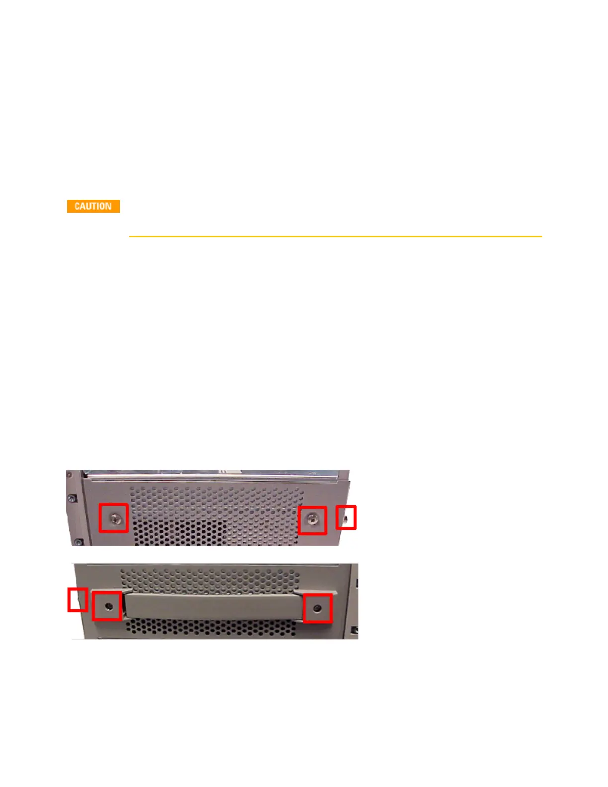
Step 2. Remove the side panels. The handle side requires a T20 driver (see Figure 4-7). The other side
panel requires a Philips pozidrive head (see Figure 4-8). There is also a screw (T10) that needs to be
removed from the rear of each side panel.
Step 3. Remove three screws using a T10 driver from the rear panel.
9 Service and Maintenance
444 Keysight N6705C Operating and Service Guide