372 Keysight Technologies N9040B UXA Signal Analyzer Service Guide
Assembly Replacement Procedures
RF Area - Options 508, 513, 526
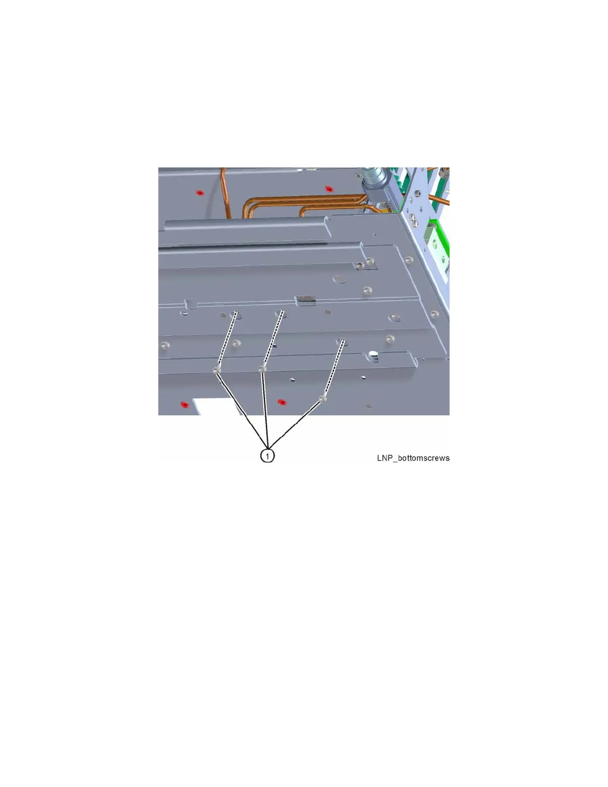
3. Refer to Figure 15-17. Remove the three screws (1) (0515-0372) that
attach the switch bracket to the chassis. Unplug the ribbon cable and the
wire harnesses from each switch. The switches and bracket can now be
removed from the chassis.
Figure 15-17 Switch Bracket Bottom Screws

 Loading...


