Keysight Technologies N9040B UXA Signal Analyzer Service Guide 373
Assembly Replacement Procedures
RF Area - Options 508, 513, 526
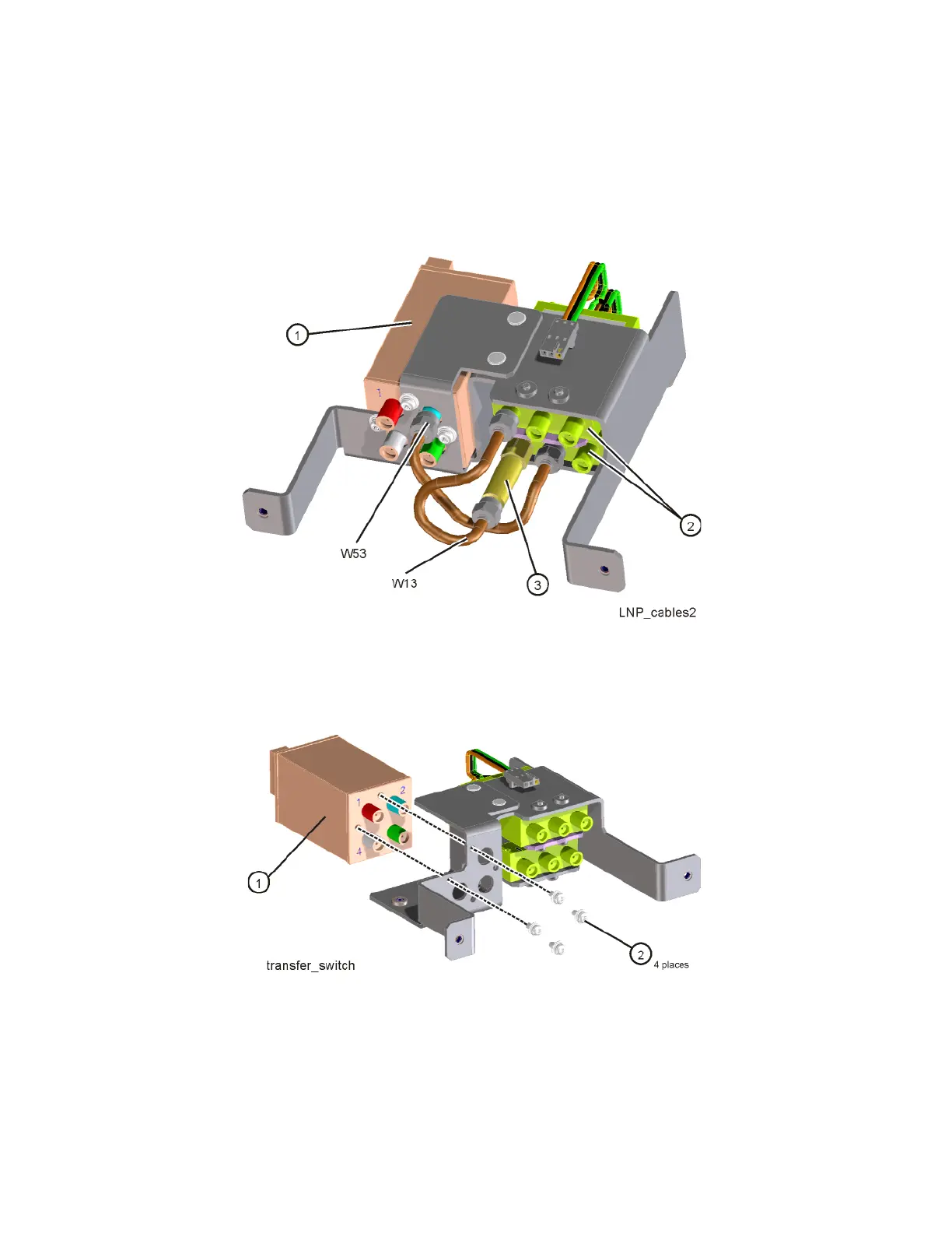
4. Refer to Figure 15-18. To remove the SW3 transfer switch (1) or the SW1
and SW2 coax switches (2) remove cables W13 and W53 as necessary to
access the switch being removed. Remove AT1 attenuator (3) if
necessary.
Figure 15-18 Transfer Switch, Coax Switches, and Cables - Options 508, 513, 526
5. Refer to Figure 15-19. To remove the SW3 transfer switch (1) remove the
four screws (2) (0515-1934) attaching the switch to the bracket.
Figure 15-19 Removing Transfer Switch from Bracket - Options 508, 513, 526

 Loading...


