Keysight Technologies N9040B UXA Signal Analyzer Service Guide 383
Assembly Replacement Procedures
RF Area - Options 508, 513, 526
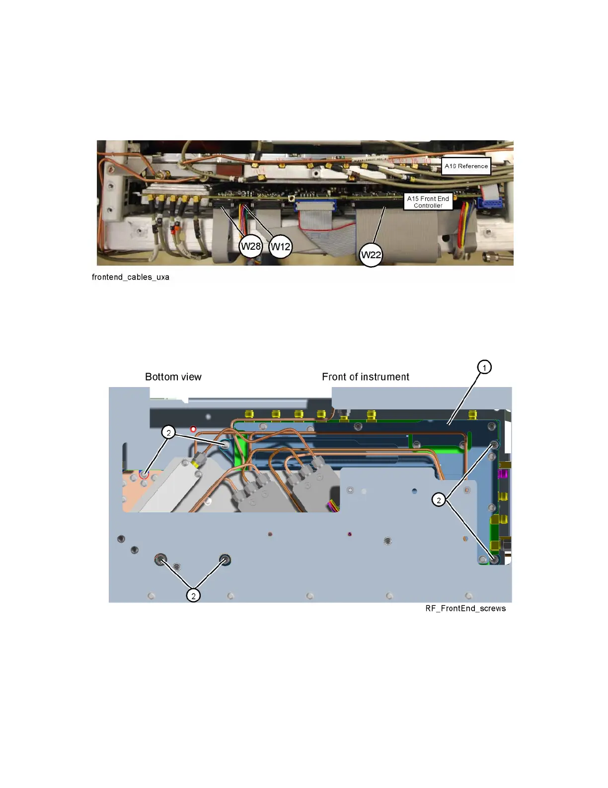
4. Refer to Figure 15-31. Unplug ribbon cables W22 and W28, and wire
harness W12 from the Front End Controller board.
Figure 15-31 Front End Controller Board Cables
5. Refer to Figure 15-32. From the bottom of the instrument, remove the six
screws (2) (0515-0372) that attach the Front End assembly (1) to the
chassis. The Front End assembly can now be removed.
Figure 15-32 Front End Assembly Bottom Screws - Removal

 Loading...


