EasyManuals Logo

Keysight N9040B Option 508 User Manual

Keysight N9040B Option 508
542 pages
To Next Page IconTo Next Page
To Previous Page IconTo Previous Page
Page #445 background imageLoading...
Page #445 background image
Keysight Technologies N9040B UXA Signal Analyzer Service Guide 445
Assembly Replacement Procedures
A4 CPU/A5 Solid State Drive
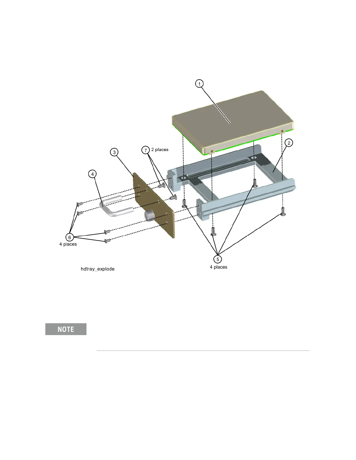
2. Refer to Figure 15-93. Remove the four screws (5) (0515-1035) from the
disk drive tray that secure the SSD (1).
Figure 15-93 Disk Drive Tray Screws
Replacement
1. Refer to Figure 15-93. Place the new SSD into the tray assembly and
attach with the four screws (5) (0515-1035). Torque to 9 inch-pounds.
2. Refer to Figure 15-92. Slide the SSD into the CPU assembly and push to
mate the connector. Secure the thumb screw to 9 inch-pounds.
Make sure not to use the 0515-0372 screw because for the PC6 processor it will cause the SSD
to interfere with the CPU memory card.

Table of Contents

Questions and Answers:

Question and Answer IconNeed help?

Do you have a question about the Keysight N9040B Option 508 and is the answer not in the manual?

Keysight N9040B Option 508 Specifications

General IconGeneral
Phase Noise-136 dBc/Hz at 1 GHz and 10 kHz offset
Input Impedance50 Ω
Input VSWR< 1.5:1
Resolution Bandwidth (RBW)1 Hz to 8 MHz
Input Power Range+30 dBm
Analysis Bandwidth40 MHz
Sweep Time1 ms to 1000 s

Related product manuals