Keysight Technologies N9040B UXA Signal Analyzer Service Guide 459
Assembly Replacement Procedures
Motherboards
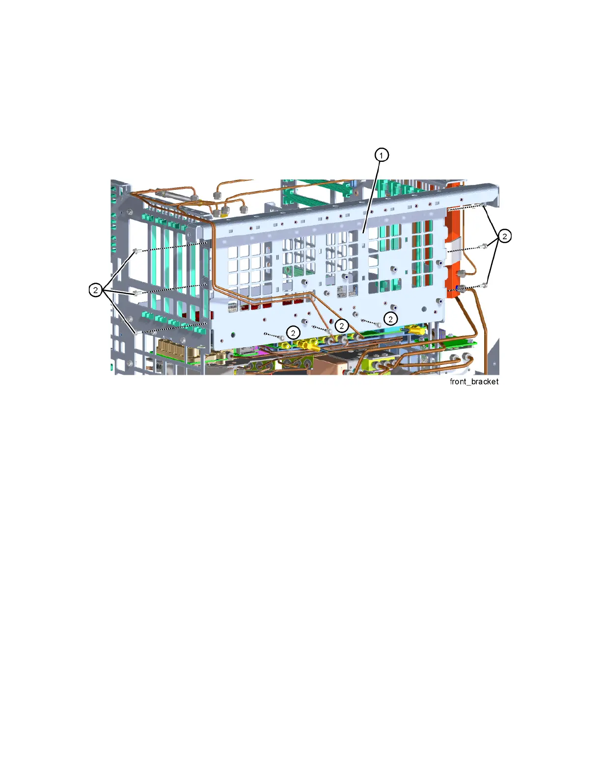
10.Refer to Figure 15-106. Remove the front bracket (1) by removing the
nine screws (2) (0515-0372).
Figure 15-106 Front Bracket Removal
11.Remove the Low Noise Path and Microwave Preselector Bypass Switches.
Refer to the “Low Noise Path and Microwave Preselector Bypass Switches”
removal procedure.
12.Remove the Front End Assembly. Refer to the “A13 RF Front End
Assembly” removal procedure.
13.Refer to Figure 15-107. Remove the seven screws (1) (0515-0372) that
attach the front motherboard bracket to the chassis. Use the ejectors to
disconnect from the rear motherboard and pull out towards the front of
the instrument to remove from the chassis.

 Loading...


