Troubleshooting Procedure
1.
Remove all remote I/O connections and front panel connections to the instrument. Verify that:
a.
the AC mains power cord is securely connected to the instrument and plugged into a live outlet
b.
the front panel Power On/Standby switch has been pushed
2.
If the standby light below the power switch is not illuminated, re-verify the items above. If all this is cor-
rect, check the AC mains power and then the internal line fuse.
3.
If the standby light is on (yellow or green), press the power button. If there is no response, replace the
front panel board because the power button on the front panel board is likely broken.
4.
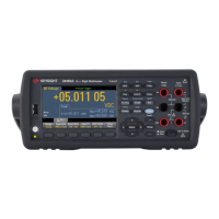
Check the voltages on the power supply. If one or more of these tests fail, disconnect the transformer
secondaries from the main board and measure the voltages from the transformer with an AC volt-
meter.
The voltage between the red and orange wires (below)should measure 7.5 to 11 VAC.
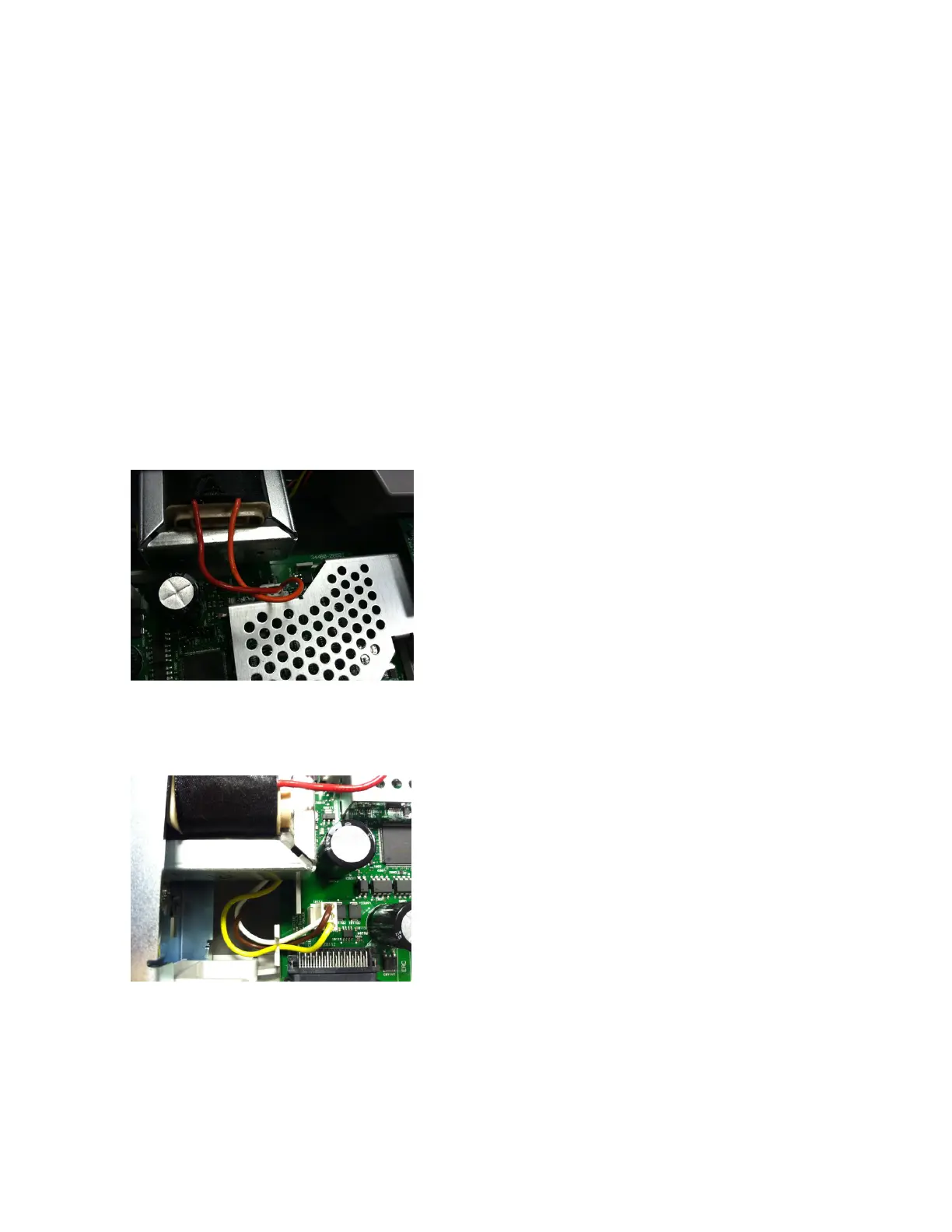
The voltage between the brown and white wires (below) should measure 11 to 15 VAC.
5.
If the voltages are correct, replace the main board; otherwise replace the transformer.
Keysight Truevolt Series Operating and Service Guide
483
Service and Repair