24 TOS5300
Turning the Power On
Turning the POWER switch on
1
Connect the included SIGNAL I/O plug to the SIGNAL I/O connector.
Connecting the SIGNAL I/O plug will release the interlock feature.
2
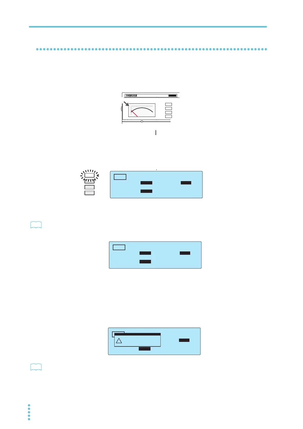
Check that the analog voltmeter is indicating “0.”
3
Turn the POWER switch on ( ).
4
Check the firmware version (Ver x.xx) that is displayed on the screen.
Check that the firmware version screen is displayed for a few seconds, that the setup
screen for setting the AC withstanding voltage test conditions is displayed thereafter,
and that the tester is then in READY mode (that the READY LED lights).
5
Check that the analog voltmeter is indicating “0.”
p.86
The first time that the POWER switch is turned on, the firmware version is displayed, and then the
setup screen for setting the AC withstanding voltage test conditions is displayed (with the factory
default settings).
The product stores the settings that are in use before it is turned off, so the next time that the
POWER switch is turned on, the TOS5300 Series starts with these settings.
About the system clock
The TOS5300 Series keeps track of the scheduled calibration date by using the internal system
clock. When the tester is turned on after the previously set calibration period has elapsed, a
message alerting you of this fact is displayed.
p.73
For details on how to set the system clock and what to do when the calibration period has elapsed,
see ”Time Settings and Calibration Management.”
T
OS5
300
ACW
AC WITHSTANDING
VOLTAGE TESTER
0
Zero indication
READY
TIMER UPPER
LOWER
0.02
mA
0.01
mA
0.50
kV
10
.5
s
ACW
TIMER UPPER
LOWER
0.02
mA
OFF
0.00
kV
0
.3
s
ACW
TIMER UPPER
LOWER
10.0
mA
0.01
mA
1.50
kV
60
.
0
s
ACW
UPPER
Calibration Protection
(Code:0x0002)
!
PROTECTION