82 TOS5300
Specifications
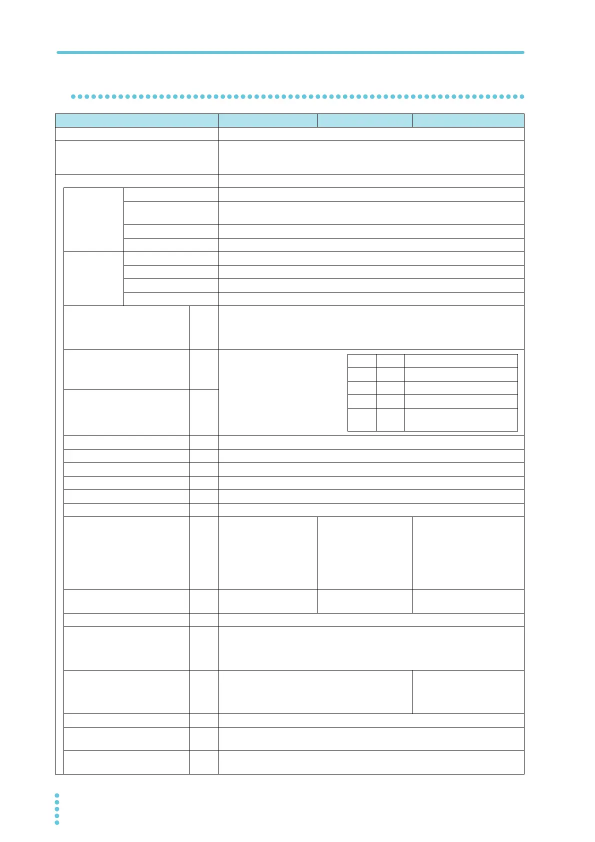
Interfaces
TOS5300 TOS5301 TOS5302
USB USB Specification 2.0, Standard Type B connector
REMOTE Front-panel 9-pin MINI DIN connector.
By connecting an optional device to this connector, you can control the starting and
stopping of tests remotely.
SIGNAL I/O Rear-panel D-sub 25-pin connector
Output
specifications
Output method Open collector output (4.5 VDC to 30 VDC)
Output withstanding
voltage
30 VDC
Output saturation voltage Approx. 1.1 V at 25 °C
Maximum output current 400 mA in total
Input
specifications
1
High-level input voltage 11 V to 15 V
Low-level input voltage 0 V to 4 V
Low-level input current 5 mA max.
Input time width 5 ms minimum
1INTERLOCK+
I
If you open the positive and negative terminals, the output is turned off, and the TOS5300
Series is switched to Protection mode.
Open: If the resistance between the terminals is 1.2 kΩ or greater.
Short: If the resistance between the terminals is 1 kΩ or less.
2 PM0
I
Panel memory selection signal.
The selection signal is latched on
the rising edge of the input strobe
signal to recall panel memory.
* The selection of memory is
prioritized over TEST SEL and
AUTO SEL.
3 PM1
I
4 NC —
5 NC —
6 NC —
7 NC —
8 NC —
9 STB I Panel memory strobe signal input terminal.
10 TEST SEL
I
NA ACW/DCW selection
signal input.
L: ACW. H: DCW.
Single test selection signal and
auto test order selection signal.
If AUTO SEL specifies single test,
L: ACW and H: IR.
If AUTO SEL specifies auto
operation, L: ACW
→IR and H:
IR→ACW.
11 AUTO SEL
I
NA NA Auto test/single test selection.
L: Single test. H: Auto test.
12 COM — Circuit common terminal.
13 INTERLOCK-
I
If you open the positive and negative terminals, the output is turned off, and the TOS5300
Series is switched to Protection mode.
Open: If the resistance between the terminals is 1.2 kΩ or greater.
Short: If the resistance between the terminals is 1 kΩ or less.
14 HV.ON
O
On during testing and when a voltage remains across
the output terminals.
On during testing, when a
voltage remains across the
output terminals, and during
auto tests (AUTO TEST).
15 TEST O On during testing (excluding when voltage is rising or falling).
16 PASS
O
On for approximately 0.2 seconds when a PASS judgment occurs.
On continuously when the PASS HOLD time is set to HOLD.
17 U-FAIL
O
On continuously when UPPER FAIL results from judgment because a value greater than or
equal to the upper limit is detected.
PM0 PM1 Recalled panel memory number
H H Memory 1
L H Memory 2
H L Memory 3
LL
Enables the selection of TEST SEL
and AUTO SEL