64 TOS5300
SIGNAL I/O Connector
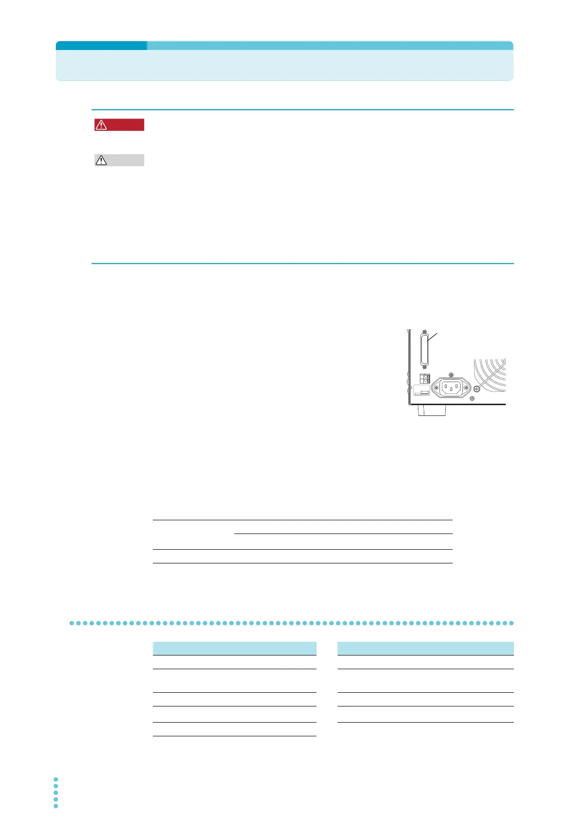
The SIGNAL I/O connector is the D-sub 25-pin connector on the rear panel.
This connector is used to start and stop tests, recall panel memory entries and test modes, and
monitor the status of the TOS5300 Series.
• Connector on the rear panel
XM3B-2522 D-sub 25-pin female connector (socket) ;
manufactured by OMRON Corporation, Screw M2.6 x 0.45
• Complies connector (plug)
D-sub 25-pin male (with fix screw M2.6)
To avoid malfunctions caused by noise, use shielded-type D-sub 25-pin connectors and a cable that
is 2.5 m or less in length.
For information about how to obtain replacement parts, contact your Kikusui agent or distributor.
For information about how to use these components, see the OMRON Corporation catalogs.
Wire and tool that are necessary to make the connection
SIGNAL I/O specifications
Possible electric shock. Ensure that all devices are off before you connect or disconnect
cables between them.
Possible damage to the internal circuitry.
• Keep the signal wire at least 500 mm away from the high-voltage test lead and the DUT.
• Do not short the output voltage circuit.
• If you use the TOS5300 Series with incomplete connections, burn outs caused by heating may
occur when the output is turned on.
• Do not touch the contacts or attach insulators to them. Doing so may reduce the quality of the
contacts or cause other problems.
• Do not short the +24 V of pin 24 to the chassis or the circuit common.
SIGNAL
I/O
COM
STATUS
OUT
+
KIKUSUI ELECTRONIC
MADE IN JAPA
STRIP-GAUGE
AWG
24-16
10 m m
AC INPUT
50/60Hz
800VA MAX
10 0
-
240V
SIGNAL I/O Connector
OMRON Cororation:
XM3B-2522
Wire Single wire: 0.32 mm (AWG28) to 0.65 mm (AWG22) in diameter
Twisted wire: 0.32 mm
2
(AWG22) to 0.08 mm
2
(AWG28)
Wire stripper A wire stripper that matches the wires listed above
Input signal Output signal
Low-active control input Open collector output
High-level input voltage 11 V to 15 V Output withstanding
voltage
30 VDC
Low-level input voltage 0 V to 4 V Output saturation voltage Approx. 1.1 V at 25 °C
Low-level input current
-5 mA maximum
1
1 Excluding the interlock signal
Maximum output current 400 mA in total
Input time width 5 ms minimum