36 TOS5300
Parts of the Screen
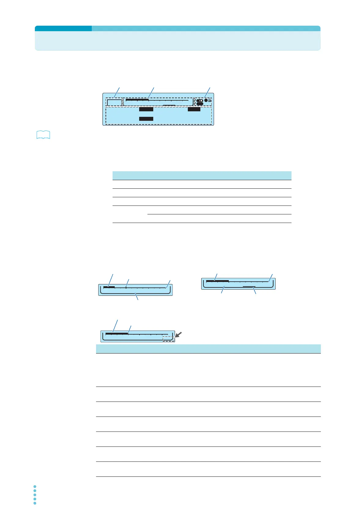
The screen that is used to set the basic test conditions is made up of the four parts shown below.
p.86
To reset the TOS5300 Series to the factory default settings, hold down SHIFT, and turn the POWER
switch on.
Test mode
This displays the currently selected test mode.
Level bar area
This displays the selected test condition setting graphically.
TIMER UPPER
LOWER
10.0
mA
0.01
mA
1.50
kV
60
.
0
s
ACW
1
USB
-
0
5.5kV
Limit Voltage 2.00kV
Data input area
Test mode Level bar area Icon area
Display Test mode
ACW AC withstanding voltage test
DCW DC withstanding voltage test
IR Insulation resistance test
AUTO Insulation resistance test → AC withstanding voltage test (IR→ACW)
AC withstanding voltage test → insulation resistance test (ACW→IR)
Test condition Display details
Voltage The test voltage is displayed on a bar graph whose maximum value is the
rated output voltage.
The set limit voltage is indicated as a tick mark on the scale. If you try to set a
test voltage that is greater than or equal to the limit voltage, “LIMIT” will blink
in the level bar area, and you will not be able to set such a voltage.
Limit Voltage The limit voltage is displayed as a value and on a bar graph whose maximum
value is the rated output voltage.
Upper Current (ACW / DCW) The upper current limit is displayed on a bar graph whose maximum value is
the rated output current.
Lower Current (ACW / DCW) The lower current limit is displayed on a bar graph whose maximum value is
the rated output current.
Upper Resistance (IR) The upper resistance limit is displayed on a bar graph whose maximum value
is the maximum of the measurement range.
Lower Resistance (IR) The lower resistance limit is displayed on a bar graph whose maximum value
is the maximum of the measurement range.
Test Time The test time is displayed on a bar graph whose maximum value is the
maximum test time.
0
5.5kV
Voltage
LIMIT
Value of the setting displayed as a bar graph
Limit voltage
LIMIT blinks
Example: Setting the test voltage
Example: Setting the limit voltage
0
5.5kV
Limit Voltage 2.00kV
Value of the setting displayed
as a bar graph
Rated value
SettingTest condition
0
5.5kV
Voltage
Value of the setting displayed
as a bar graph
Test condition
Limit voltage
Rated value
Example: Setting a voltage that is greater than or equal to the set limit voltage