TOS5300 27
Connecting to the Device under Test (DUT)
2
Installation and Preparation
4
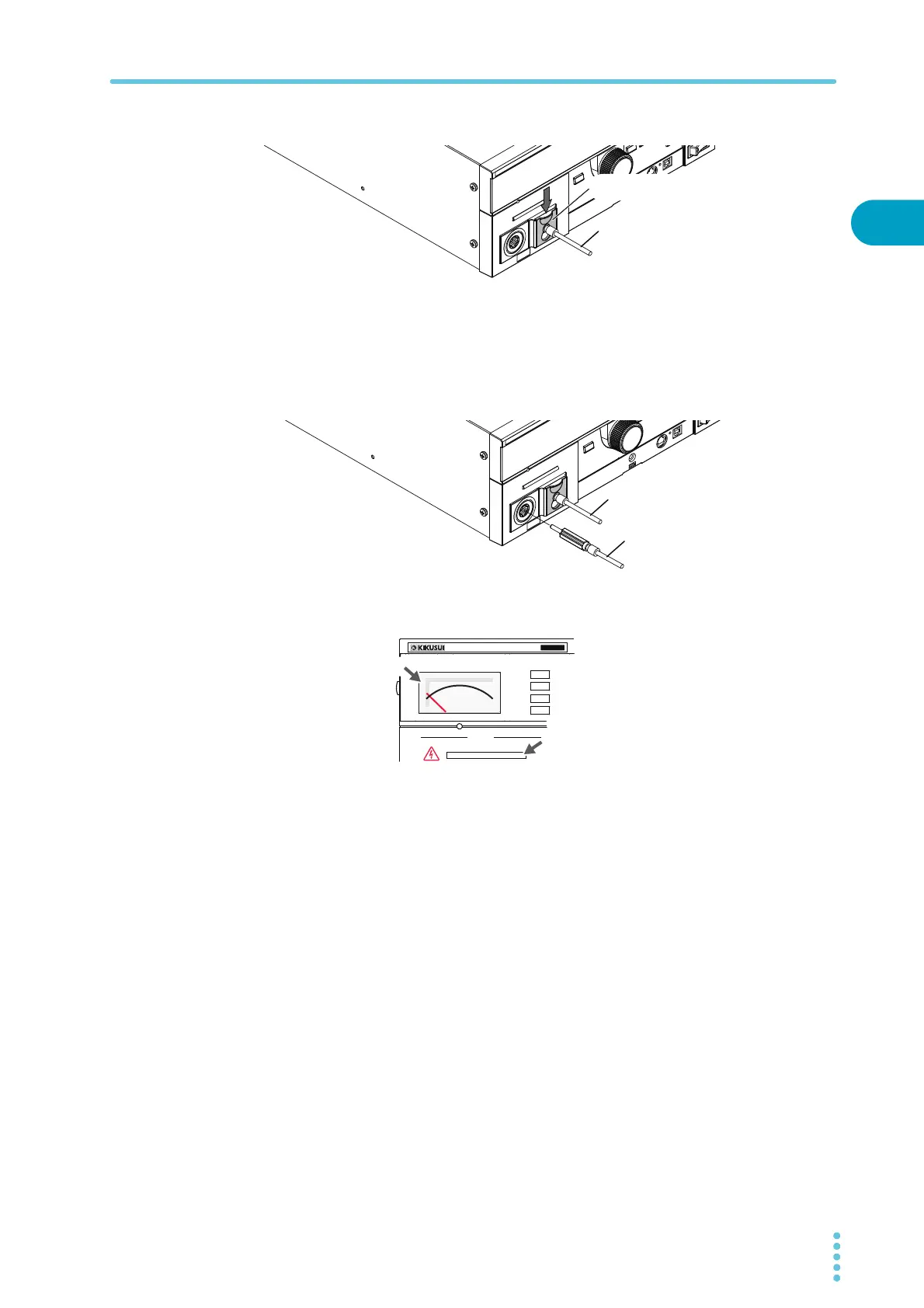
Lower the cable lock to secure the lead in place.
5
Connect the LOW test lead (black) to the DUT.
6
Connect the HIGH VOLTAGE test lead (red) to the DUT.
7
Connect the HIGH VOLTAGE test lead (red) to the front-panel HIGH VOLTAGE
terminal.
8
Check that the analog voltmeter is indicating “0” and that the DANGER LED is
off.
Reducing the effect of noise
Noise may be generated if the outputs are shorted or if the DUT insulation is damaged. Electronic
devices in the surrounding area may malfunction due to the effect of this noise. To reduce the effect
of noise, connect a toroidal core or a resistor of approximately 470 Ω between the tips of the HIGH
VOLTAGE and LOW test leads and the DUT. Connect the toroidal core or resistor as close to the DUT
as possible.
If you are connecting a toroidal core, it is effective to wrap the test leads two to three times around
a type of core that can be snapped on and that is often used with power cables. This type of core is
usually approximately 20 mm in diameter.
If you are connecting a resistor, pay close attention to the power rating of the resistor. When the
upper limit is 10 mA or less, connect a resistor of approximately 470 Ω (3 W, 30 kV impulse
withstanding voltage). Because this resistor causes the voltage to fall, the voltage that is actually
applied to the DUT is slightly lower than the voltage that is generated from the product’s output
terminals (when a 10 mA current flows, the voltage falls approximately 10 V).
These methods are extremely useful in reducing the effect of noise.
LOW test lead (black)
Lower the cable lock.
LOW test lead (black)
HIGH VOLTAGE test lead (red)
OUTPUT
DANGER
T
OS5
300
ACW
AC WITHSTANDING
VOLTAGE TESTER
0
Off
Zero indication