Stratos Multi E401N
132
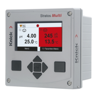
Sensor Diagram
Note: Function active for pH and oxygen sensors
The sensor diagram clearly indicates the status of the parameters in the connected sensor, including
the calibration timer.
Inactive parameters are shown in gray and set to 100% (e.g. disabled calibration timer).
The parameter values should lie between the outer (100%) and inner (50%) hexagon. A warning
signal flashes if a value drops below the inner hexagon (<50%).
Access in: Diagnostics
[I] [II] [Sensor]
Sensor Diagram
Display example:
Sensor Diagram
Back
1 - Slope
2 - Zero Point
3 - Glass Impedance
4 - Response Time
5 - Calibration Timer
6 - Sensor Wear
1
3
2
5
4
6
Calibration/Adjustment Record
The calibration/adjustment record shows the data from the last calibration/adjustment performed on
the currently connected sensor.
Access in: Diagnostics
[I] [II] [Sensor]
Cal/Adj Record [Process Variable]
Temp. Offset Log
The temp. offset log shows the data from the last temperature equalization performed on the
currently connected sensor.
Access in: Diagnostics
[I] [II] [Sensor]
Temp Offset Log
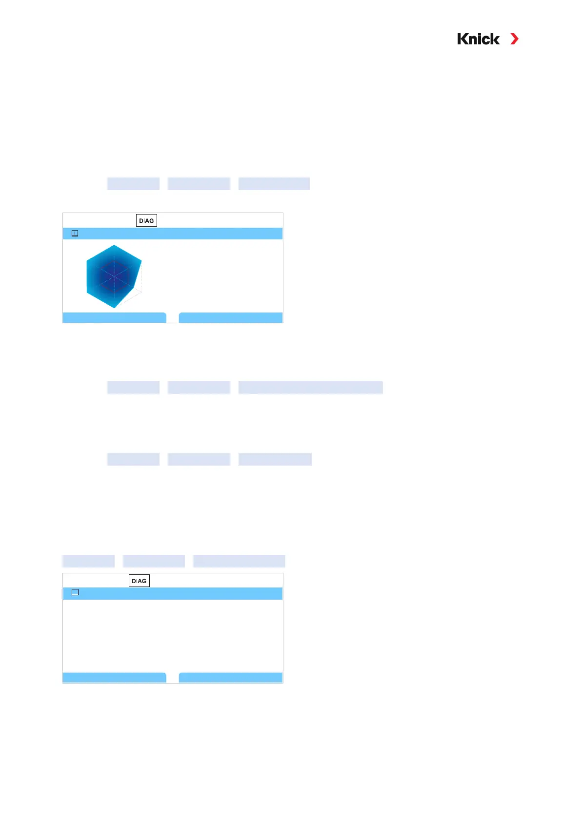
Sensor Wear Monitor
Note: Function active for digital sensors
The sensor wear monitor shows the sensor operating time and the maximum temperature during the
operating time, as well as wear and the forecast remaining time. When using oxygen sensors,
the number of membrane replacements and calibrations is also displayed:
Diagnostics
[I] [II] [Sensor]
Sensor Wear Monitor
Sensor Wear Monitor
Back
Operating Time 68 d
Back to Meas.
I
Wear
Remaining Lifetime
Max. Temperature
9.5 %
661 d
32°C