8
INFORMATION ABOUT OVERHAULING
EN 102
Grinding of surface
A1
is not permitted
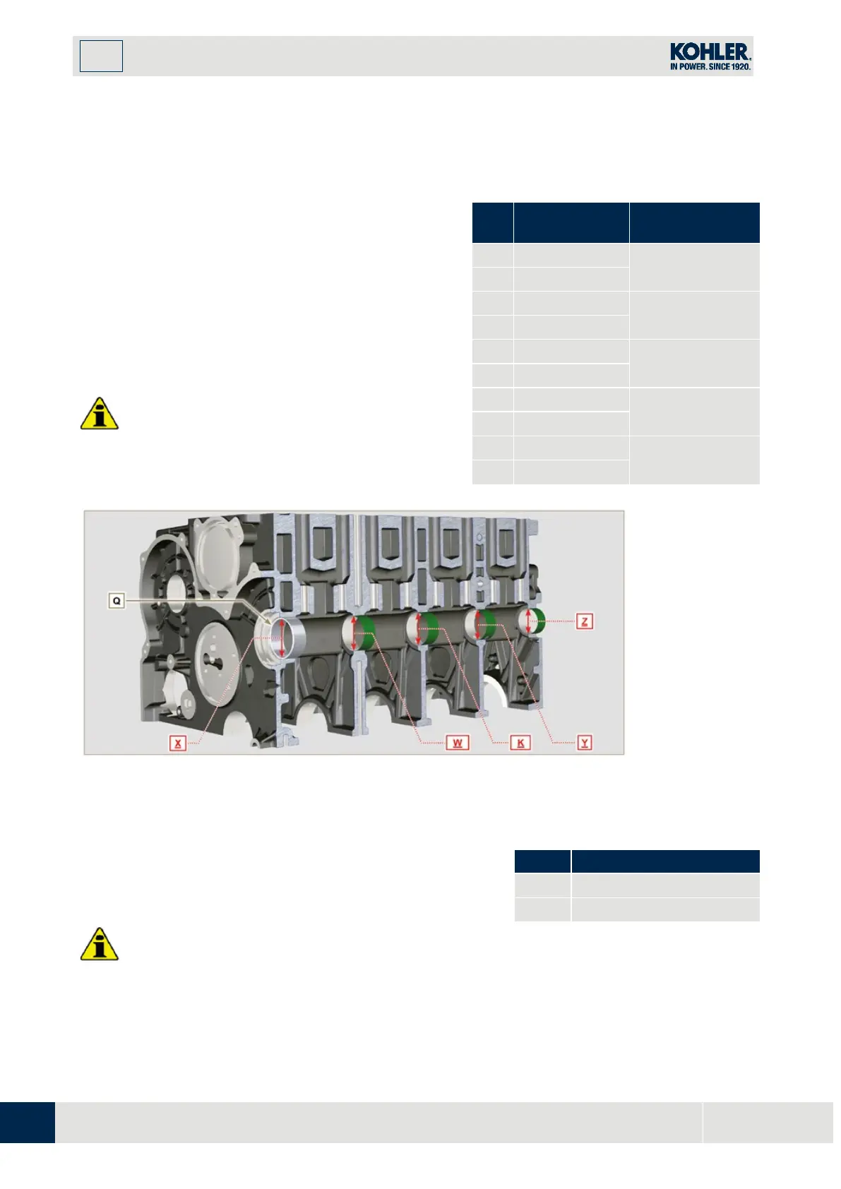
8.2.4 4-cylinder camshaft housing check
The camshaft housings only contain the timing system
side bushing Q.
Use an internal dial gauge to measure the diameters of
housings X - W - K - Y - Z.
With a micrometer, measure the diameters of gudgeon
pins X1 - W1 - K1 - Y1 - Z1 (Fig. 8.4). According to the
values measured, calculate the clearance between the
housing and gudgeon, which is to observe the values in
Tab. 8.2a.
The MAX value of wear allowed is 0.120 mm
Important
•
Tab. 8.2a details the dimensional values of new
components only.
Tab 8.2a Housing and camshaft gudgeon
dimensions.
REF.
0.040 - 0.085
0.060 - 0.105
0.060 - 0.105
0.060 - 0.105
0.060 - 0.105
Fig 8.3
8.2.5 Camshaft control for 4 cylinder engine
W
ith a micrometer, measure the maximum dimensions of intake
camshaft
R
and exhaust camshaft
S (Tab. 8.2b)
.
The
MAX
value of wear allowed is
0.1 mm
.
Important
Tab. 8.2b details the dimensional values of new components
Tab 8.2b Camshaft dimensions.

 Loading...


