ASSEMBLY INFORMATION
9
115
EN
1.
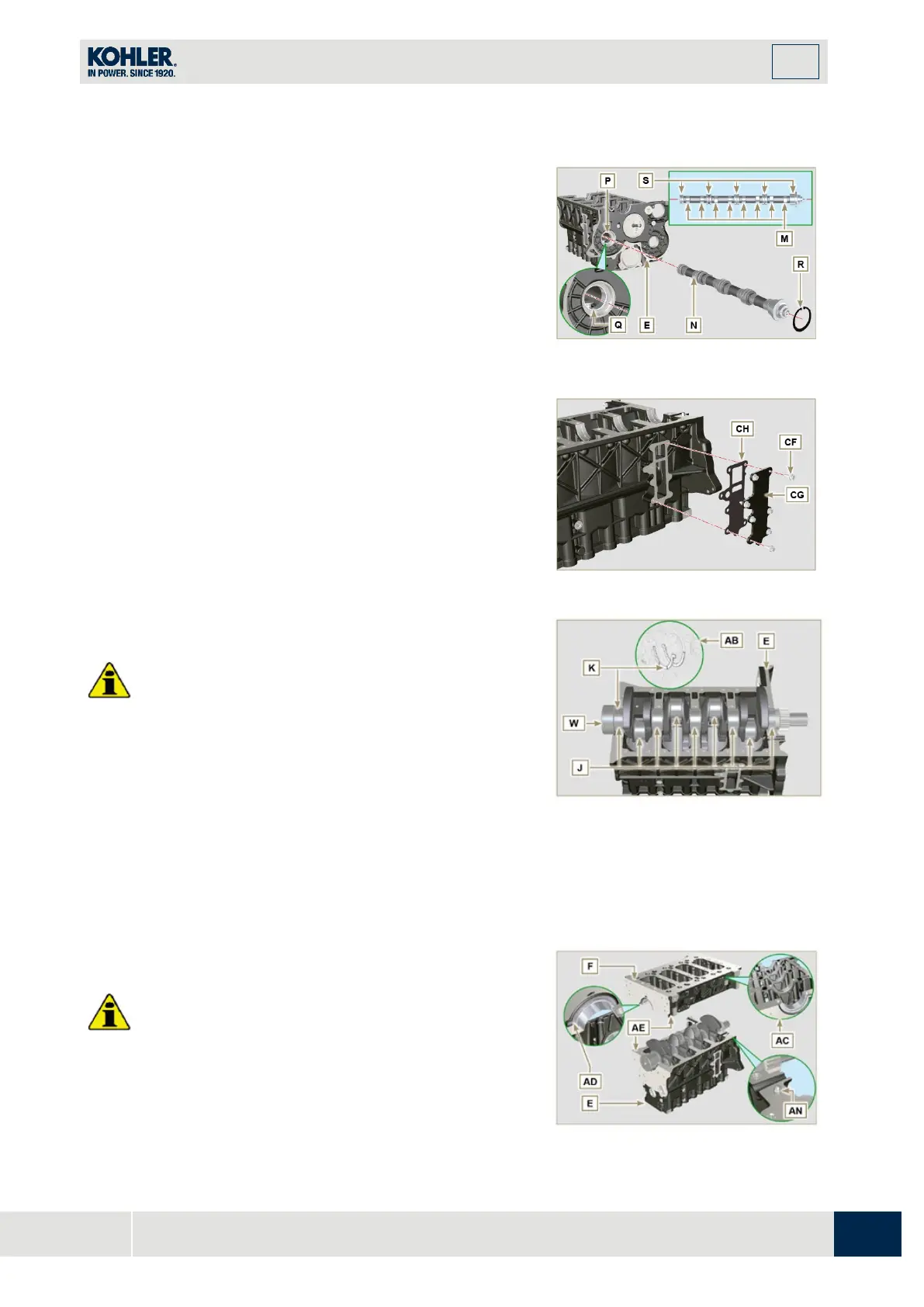
Check that the bushing Q is correctly fitted.
2.
Lubricate the pins L, the cams M of the camshaft N, al
l
the housing P (Par. 8.2.4 and Par. 8.2.6) and the
bushing Q with oil.
3.
Insert the camshaft N all the way into its housing P.
4.
Fit the lock ring R on to the crankcase E to hold the
position of the camshaft N.
5.
Manually rotate the camshaft N ensuring that it is free.
Fig 9.4
9.3.4 Vent compartment closure lid
1.
With the screws CF tighten the cover CG and the
gasket CH (tightening torque to 10 Nm).
Important
•
Carry out the checks described in Par. 8.4.1 and Par.
8.4.2.
1.
Check that the crankshaft half-bearings are mounted
correctly on the upper crankcase E.
2.
Lubricate the main journal and crankpin J, with oil.
3.
Insert the crankshaft W into its seat on the upper
crankcase E.
4.
Insert the 2 shoulder half-rings K, between th
e
cr
ankshaft W and the upper crankcase E (AB detail).
Fig 9.6
Important
•
Before proceeding to the assembly of the piston and
connecting rod, carry out the checks described in Par.
8.5.1.
Fig 9.7

 Loading...


