9
ASSEMBLY INFORMATION
EN 116
Check that the crankshaft half-bearings are mounted
correctly on the lower crankcase F (AC detail).
2.
Assemble the 2 shoulder half-rings AD onto the lower
crankcase F applying two drops of oil to keep them in
their seat.
3.
Check that the coupling surfaces AE are free from dirt
and grit.
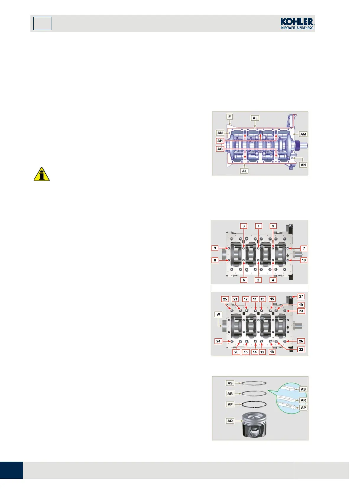
Spread a bead of
of approx
mm thickness on the surface AM of the upper
crankshaft half C being careful not to block the oil feed
grooves AG and the return oil sump AH.
5.
Join the two crankshaft halves E and F observing the
guide pins AN.
I
mportant
•
Failure to follow the bolting procedures compromises
the functionality of the engine and can cause damag
e
to people and property.
Fig 9.8
6.
Tighten the fastening screws strictly following the
sequence and the tightening torque indicated.
Tightening Screws
Torx M12x1,25
(from the
n° 1
to the
n° 10
):
CYCLE 1 - with a torque of
40 Nm
;
CYCLE 2 - with a torque of
70 Nm
;
CYCLE 3 - with a torque of
120 Nm
.
Tightening Screws
Torx M8
(from the
n° 11
to the
n°
27
):
CYCLE 4 - with a torque of
20Nm
;
CYCLE 5 - with a torque of
35
Nm
;
7.
Perform the operations described in Par. 8.4.2.
8.
Check that crankshaft W rotates smoothly.
Fig 9.9
9.3.7 Piston rings
1.
Perform the operations described in Par. 8.5.3.
2.
Put the scraper ring AP onto the piston AQ.
3.
Put the 2° seal ring AR on the piston AQ.
4.
Put the 1° seal ring AS onto the piston AQ.

 Loading...


