ASSEMBLY INFORMATION
9
127
EN
0.251 - 0.375
3
4.
Based on the value detected at point 3, select th
e
r
elevant gasket T as shown in the Tab. 9.2 (Fig. 9.47
detail U).
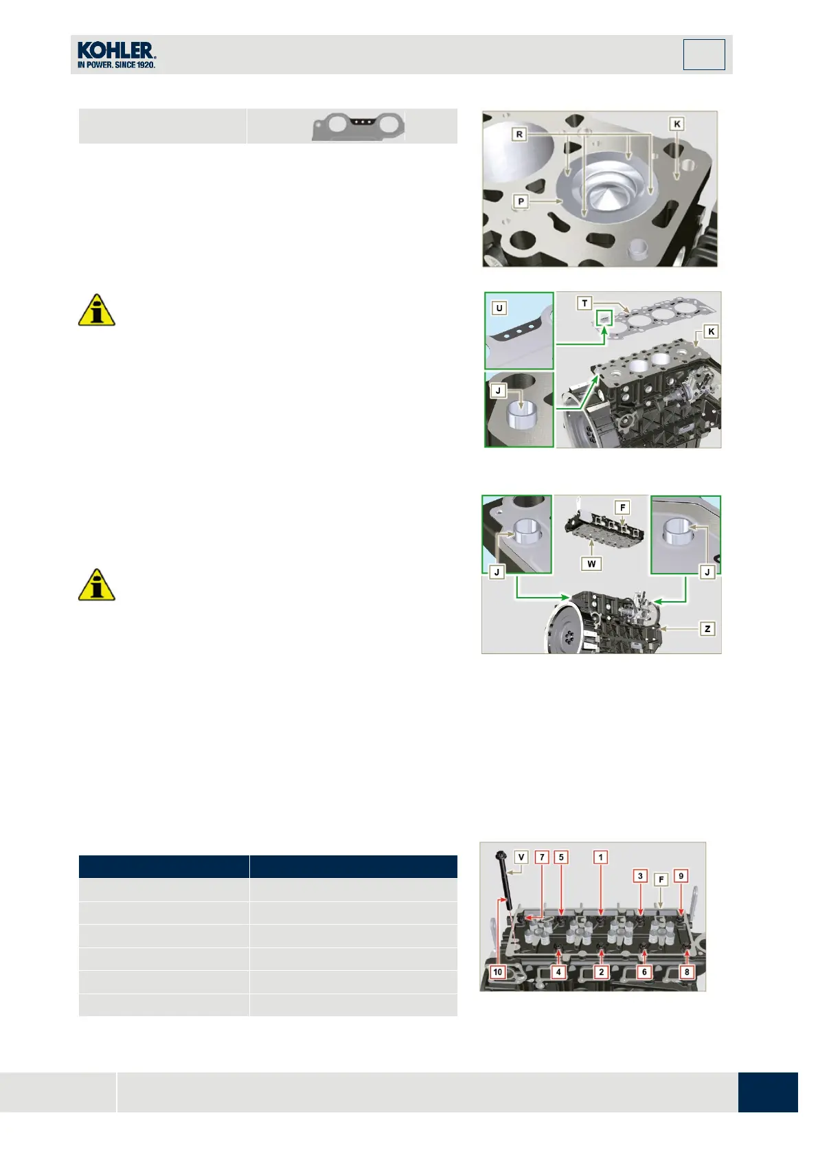
5.
Check that the crankcase surface K and the gasket T
are completely free of dirt and grit.
Important
•
The head gasket must be replaced for each
assembly.
6.
Position the gasket T on the surface K with referen
ce
to
the centering bushings J.
Fig 9.46
Check that the surface head W is free from impurities.
8.
Position the head F on the crankcase Z wi
th
r
eference to the centering bushings J.
I
mportant
•
The fastening bolts V must be replaced every tim
e
they are assembled.
•
Failure to adhere to the bolt fixing procedures may
compromise the functionality of the engine, and also
may cause damage to persons and property.
•
Tighten capscrews V observing the cycles, tightening,
and subsequent rotation as indicated in Tab. 9.3.
9.
Secure the head F by tightening the screws V strictly
following the sequence indicated in the Fig. 9.50 an
d
the tightening torque indicated in the Tab. 9.3.
Fig 9.48
Fig 9.50

 Loading...


