9
ASSEMBLY INFORMATION
EN 128
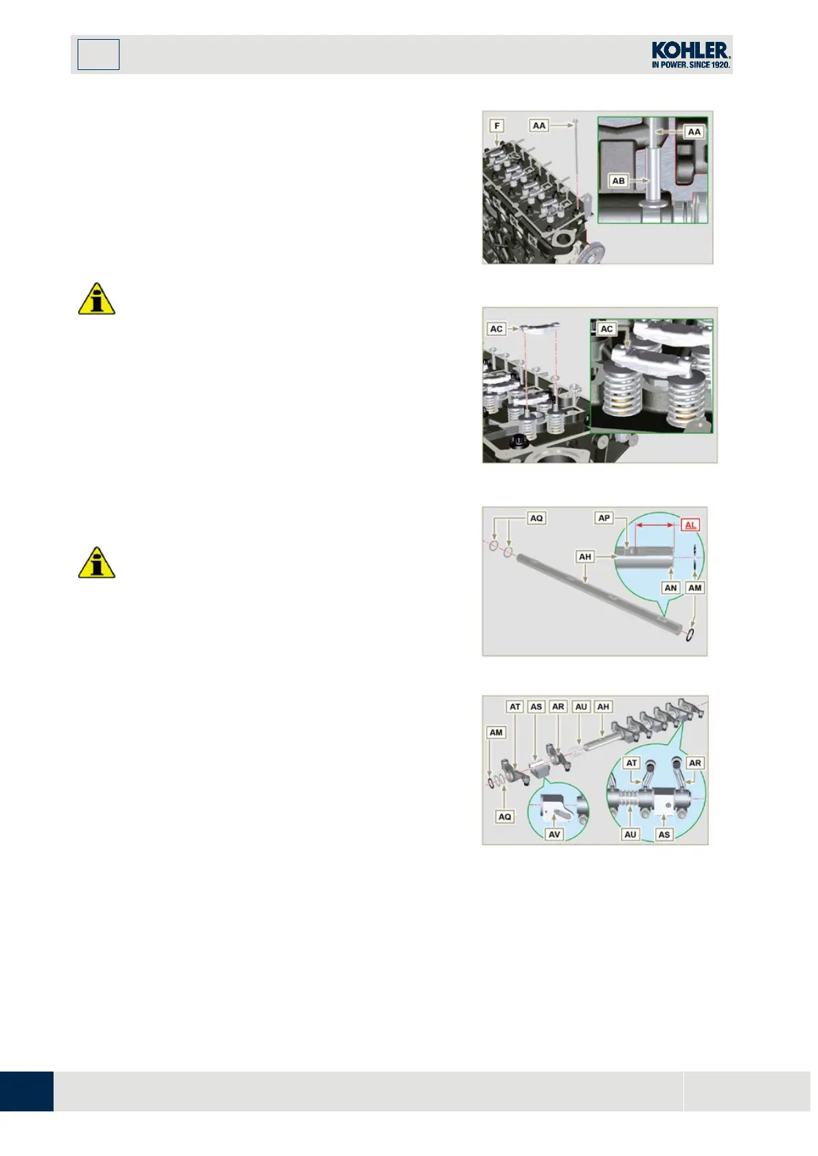
9.7.6 Rods and valve bridges
1.
Insert the rocker control rods AA into the niches of
the head F.
I
mportant
•
Properly centre the rods AA into the spherica
l
ho
using of the camshaft tappets AB.
2.
Mount the valve bridge AC on to the pairs of
discharge and suction valves.
Important
•
To correctly position the rocker arms, turn the rocke
r
a
rm pin AH with the lower height AL towards the
timing system side as in Fig.9.54.
•
The discharge rocker arm AT is shorter than the
suction arm AR.
1.
Fit the lock ring AM into the seat AN of the rocke
r
a
rm pin AH.
2.
Position the pin AH with the screw support sur
face
AP facing upwards and insert the 2 shoulder rings
AQ.
3.
Insert in sequence the suction rocker arm AR, the
holder AS and the discharge rocker arm AT in the pi
n
AH.
4.
I
nsert the spring AU in the pin AH.
5.
Repeat points 3, 4 for all the rocker arms.
NOTE: The holder AV must be fitted with the last pair
of rocker arms towards the flywheel.
6.
Insert 2 shoulder rings AQ and the lock ring AN to
lock all the components inserted in the pin AH.
NOTE : The spring AU ensures that the supports AS
and AV are kept in place.
Fig 9.54
F
ig 9.55

 Loading...


