2
TECHNICAL INFORMATION
EN 24
The fuel filter is situated on the crankcase of the engine or it may
be assembled on the frame of the vehicle.
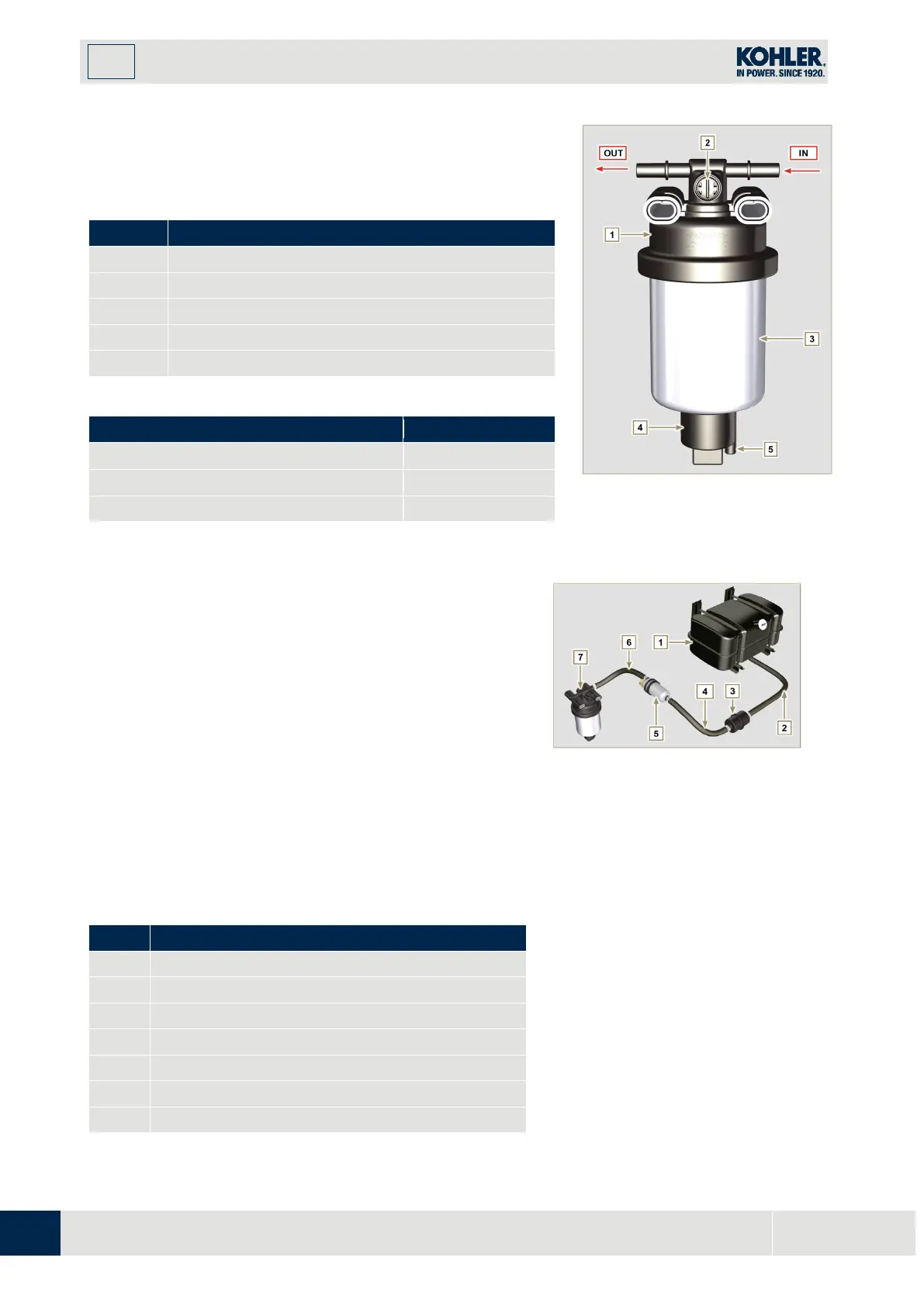
Tab 2.16
Fuel filter support cartridge
Tab 2.17 Cartridge characteristics
Fig 2.9
2.9.6
Electric fuel pump (optional)
W
hen the electric fuel pump is installed in a diesel engine, one
must:
1.
Remove any filters installed on the inlet of the electri
c
fuel pump;
2.
Insert a pre-filter between the tank and the electric
pump;
3.
The electric pump must be installed on the application
at a height from the minimum tank level such as to
generate a MAX. pressure drop equal to a column of
500 mm of fuel;
4.
Insert a shut-off valve to prevent dry operation due to
the emptying of the intake manifold;
5.
The electric pump must guarantee a supply pressure at
the inlet positive in all conditions.
Tab 2.18
Arrival pipe from the tank
Flow pipe from pre-filter to electric pump
Flow pipe to the fuel filter
Fig 2.10

 Loading...


