TECHNICAL INFORMATION
2
31
EN
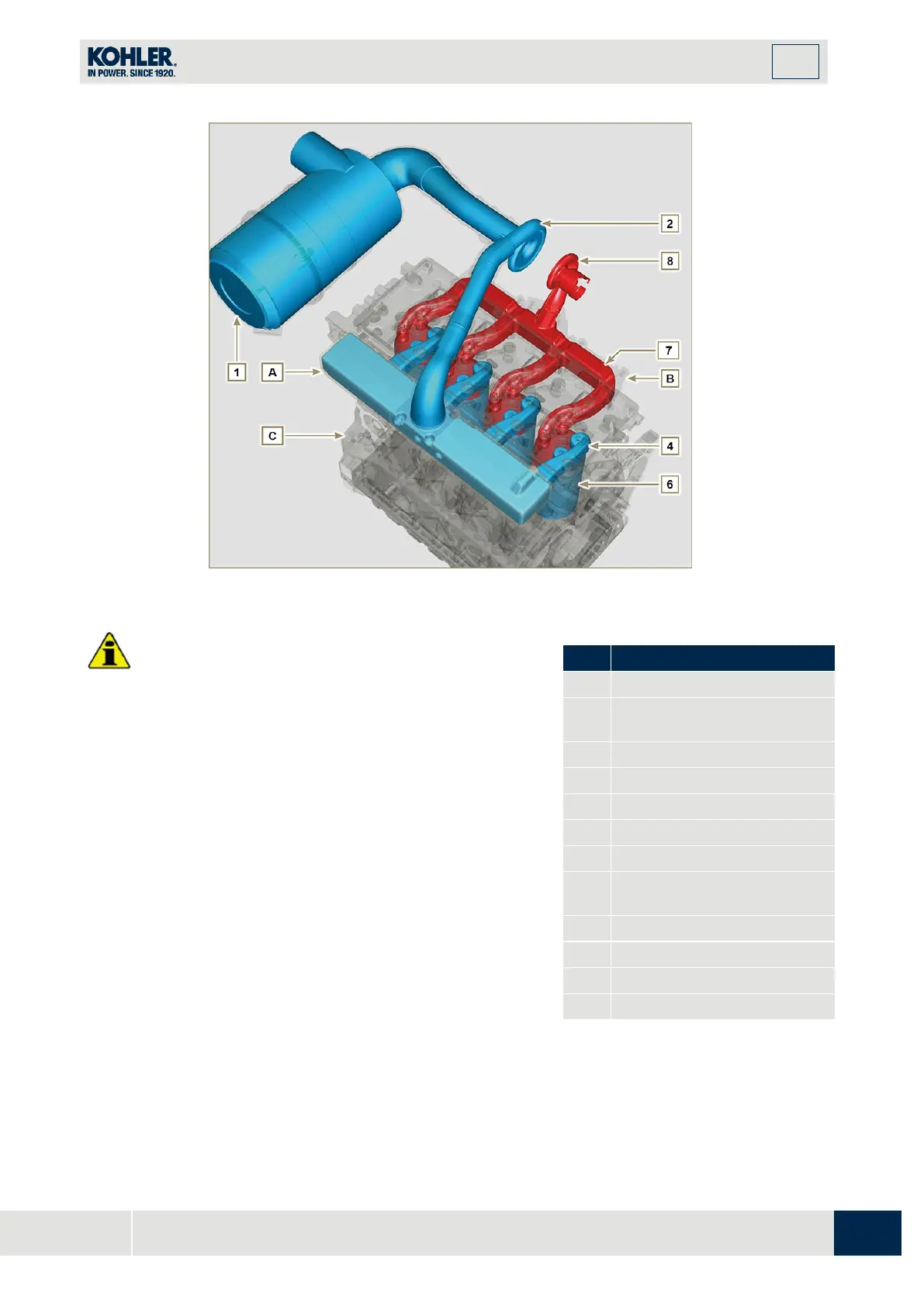
Fig 2.23
•
The air temperature inside the intake manifold must
never exceed that of the environment by 10°C.
Clean air is sucked by the turbocharger, which compresses it in
the intake manifold and via ducts in the cylinder head, enters the
cylinders. Compressed air inside the cylinders and mixed with
the fuel transforms into Gas after combustion. The gas is
expelled from the cylinders and sent to the exhaust manifold.
The exhaust manifold sends the gases to the turbocharger's
body (the expelled gases activate the turbine), the gases then
proceed towards the exhaust line to be definitely expelled.
2
Air in compression in the
turbocharger
8
Exhaust gas from the
turbocharger
Exhaust muffler (optional)
2.12.1 Air filter (optional)

 Loading...


