INFORMATION FOR DISASSEMBLY
7
95
EN
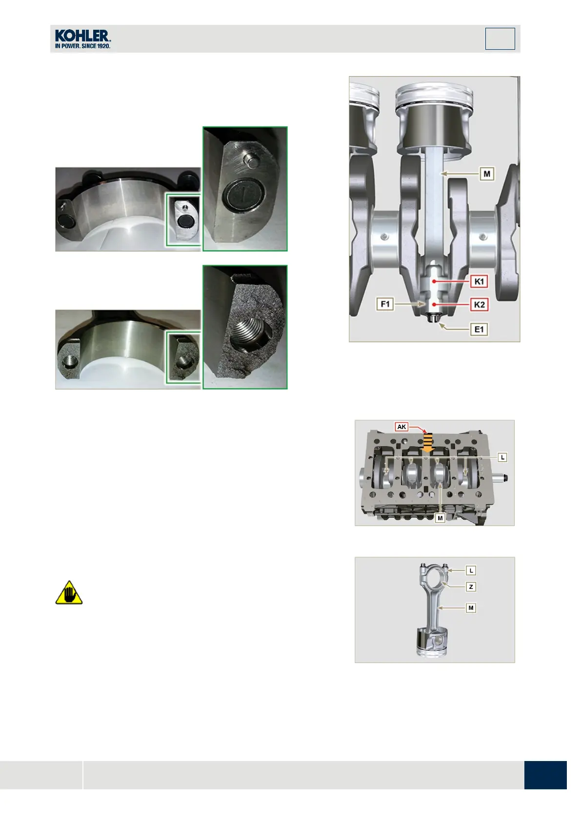
NOTE
: coupling cap
F1
on the connecting rod can be carried
out with centring taper pins
(Fig. 7.46b)
or broken (
Fig. 7.46c
-
without centring taper pins).
Fig. 7.46b
Fig. 7.46c
Fig 7.46a
3.
P
ull out the connecting rod - piston assembly from
position 2 and 3 by manually applying pressure on the
connecting rod big end L in the direction of arrow AK.
4.
Couple the connecting rod big end caps L with the
relevant piston and connecting rod unit M.
5.
Turn capscrew AM and rotate the crankshaft by 180°.
6.
Repeat points 2 to 5 to disassemble the connecting rod-
piston assembly to position 1 and 4.
Warning
•
The connecting rod half-bearings Z are made of special
material. Therefore, they must be replaced every tim
e
they are removed to prevent seizures.

 Loading...


