191
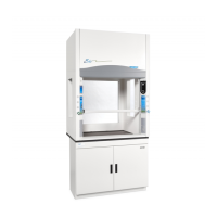
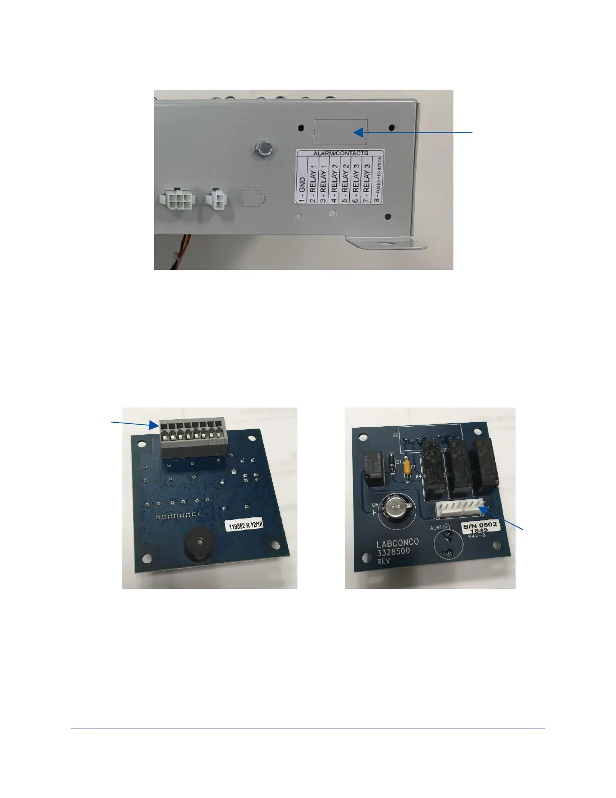
5. Locate the gray rectangle connector labeled as J2 (see Figure 22-3) on the
Alarm/Relay Contact board supplied with the kit. This connector shows through
the knock-out opening previously removed on the electronics control module.
Note the location of the connector J1 (Figure 22-4) on the opposite side of the
board for use later.
6. Install the Alarm/Relay Contact board inside the electronics module using the
screws, standoffs, lockwashers, and nuts included with the kit. First, secure each
standoff inside the electronics module with a screw and lockwasher (screw and
lockwasher on outside of module). Then, place circuit board over standoff’s male
threads, and secure board with the four nuts.