192
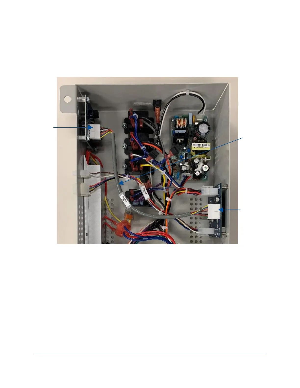
7. Locate the wire harness included in the kit. Connect it between the Alarm/Relay
Contact circuit board’s J1 connector and the I/O Transition board’s J6 connector.
See Figure 22-5 for reference.
8. Re-secure the electronics module to the top of the biosafety cabinet.
If not utilizing the Relay Contacts, stop here.