EasyManuals Logo

Labconco Logic+ A2 User Manual

Labconco Logic+ A2
201 pages
To Next Page IconTo Next Page
To Previous Page IconTo Previous Page
Page #193 background imageLoading...
Page #193 background image
193
9. Connect user-supplied wires to the appropriate contacts as desired. Use 22-24
AWG wires ONLY. Strip insulation back from wire end 0.25 inches (6 mm).
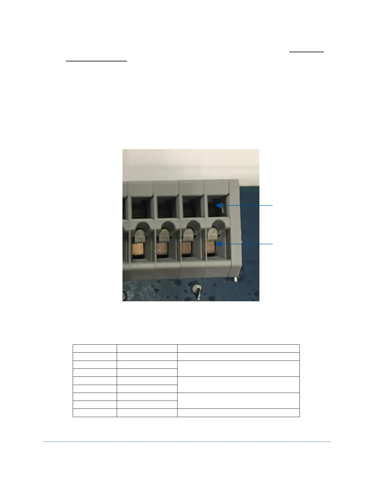
10. Using a small jeweler’s flat blade screwdriver or similar instrument, push the
screwdriver into the release opening (see Figure 22-6), and rotate the
screwdriver up (away from the wiring connection) slightly. This will open the
clamp. Slide the stripped wire end into the appropriate slot on the connector,
then remove the screwdriver. To release a wire, reinsert the screwdriver, rotate it
up (away from the wire), and pull the wire straight out from the connector. See
Figure 22-6 for reference.
The relay contact closes when the condition is present on the biosafety cabinet. See
the pinout configuration below in Table 22-1 to properly connect the wires.
Figure 22-6
Release Opening
Stripped wire slot
on connector
Position
Contact Label
Condition/Description
1
GND
Common used with +12 VDC
2
RELAY 1
Closes upon Blower start (remains
closed while Blower at Normal Speed)
3
RELAY 1
4
RELAY 2
Closes upon any Alarm Condition
5
RELAY 2
6
RELAY 3
Closes upon Blower at Reduced
Speed (Night Setback sash closed)
7
RELAY 3
8
FUSED +12 VDC
+12 VDC supplied (Fused @ 0.5 A)
Table 22-1

Table of Contents

Questions and Answers:

Question and Answer IconNeed help?

Do you have a question about the Labconco Logic+ A2 and is the answer not in the manual?

Labconco Logic+ A2 Specifications

General IconGeneral
BrandLabconco
ModelLogic+ A2
CategoryLaboratory Equipment
LanguageEnglish

Related product manuals