3: Installation
SLC™ 8000 Advanced Console Manager User Guide 37
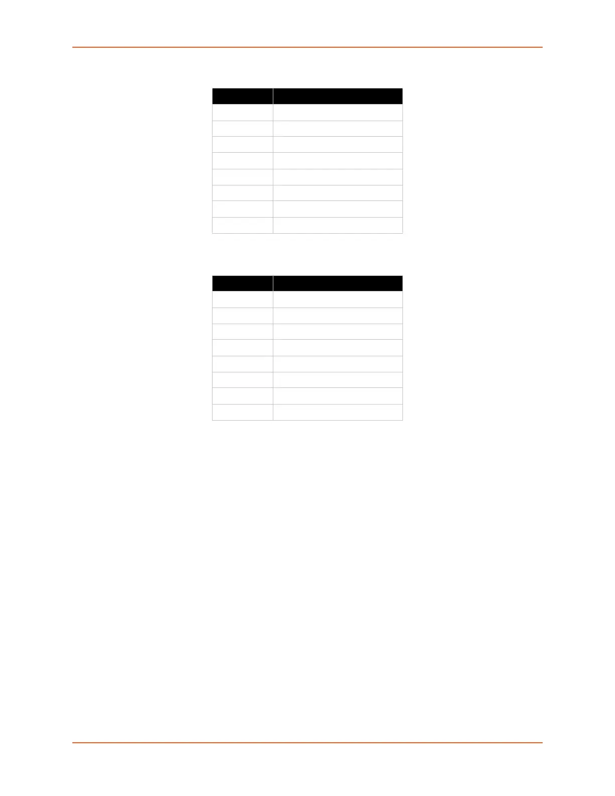
Table 3-5 Console Port and Device Port - Reverse Pinout Disabled
Table 3-6 Device Port - Reverse Pinout Enabled (Default)
To connect to a USB device port:
1. Connect the USB type A connector of a USB cable to a device port.
2. Connect the other end of the USB cable to a USB console port.
Figure 3-7 shows a sample I/O module installation with two 16-port RJ45 I/O modules and one
16-port USB I/O module, and how the device ports correspond to the buttons on the Dashboard.
Pin Number Description
1 RTS (output)
2DTR (output)
3 TXD (output)
4Ground
5Ground
6 RXD (input)
7 DSR (input)
8 CTS (input)
Pin Number Description
1 CTS (input)
2 DSR (input)
3 RXD (input)
4Ground
5Ground
6 TXD (output)
7DTR (output)
8 RTS (output)
 Loading...