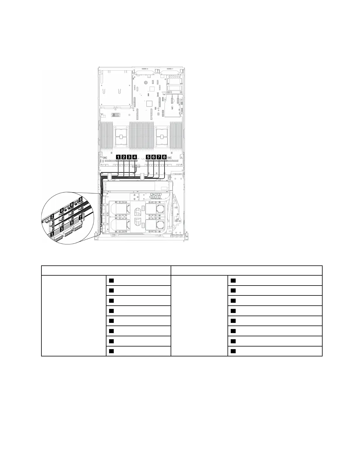
Retimer assembly signal cables
Connect the retimer assembly signal cables as illustrated.
Figure 67. Retimer assembly cable routing (signal cables) – Configuration G
From To
Retimer assembly
1 MCIO connector A
System board
1 PCIe connector 10
2 MCIO connector B 2 PCIe connector 9
3 MCIO connector C 3 PCIe connector 8
4 MCIO connector D 4 PCIe connector 7
5 MCIO connector E 5 PCIe connector 6
6 MCIO connector F 6 PCIe connector 5
7 MCIO connector G 7 PCIe connector 4
8 MCIO connector H 8 PCIe connector 3
Chapter 3. Internal cable routing 119

 Loading...


