Step 1. Prepare your server.
a. Remove the top cover. See “Remove the top cover” on page 225.
Step 2. Disconnect the front USB, video and external LCD diagnostics handset cables of the front I/O
module from their respective connectors on the system board. See “System-board connectors” on
page 34 for more details.
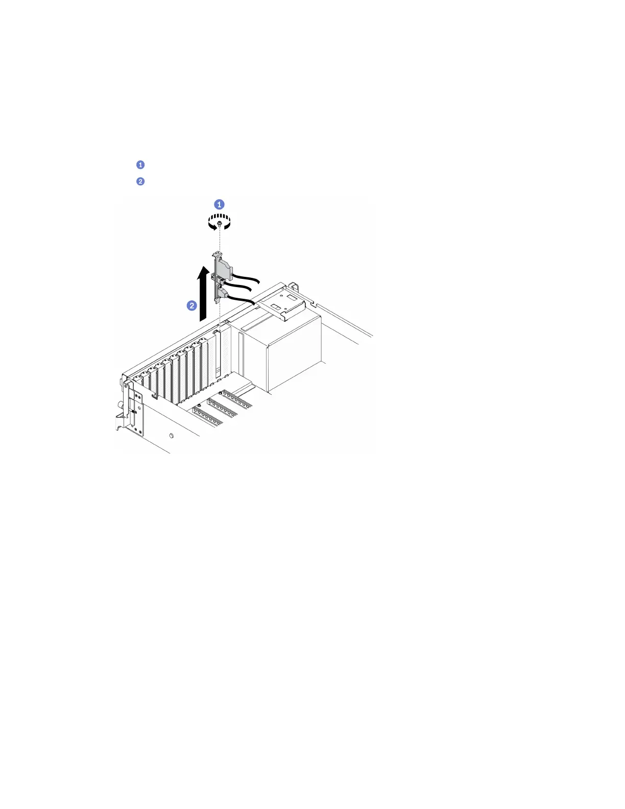
Step 3. Remove the front I/O module.
a.
Remove the front I/O module retention screw.
b.
Lift the front I/O module out of the chassis.
Figure 94. Removing the front I/O module
After you finish
1. Install a replacement unit or a slot bracket. See “Install the front I/O module” on page 151.
2. If you are instructed to return the component or optional device, follow all packaging instructions, and
use any packaging materials for shipping that are supplied to you.
Install the front I/O module
Follow instructions in this section to install the front I/O module.
About this task
Attention:
• Read “Installation Guidelines” on page 121 and “Safety inspection checklist” on page 122 to ensure that
you work safely.
• Touch the static-protective package that contains the component to any unpainted metal surface on the
server; then, remove it from the package and place it on a static-protective surface.
Watch the procedure. A video of the installation and removal process is available:
Chapter 4. Hardware replacement procedures 151

 Loading...


