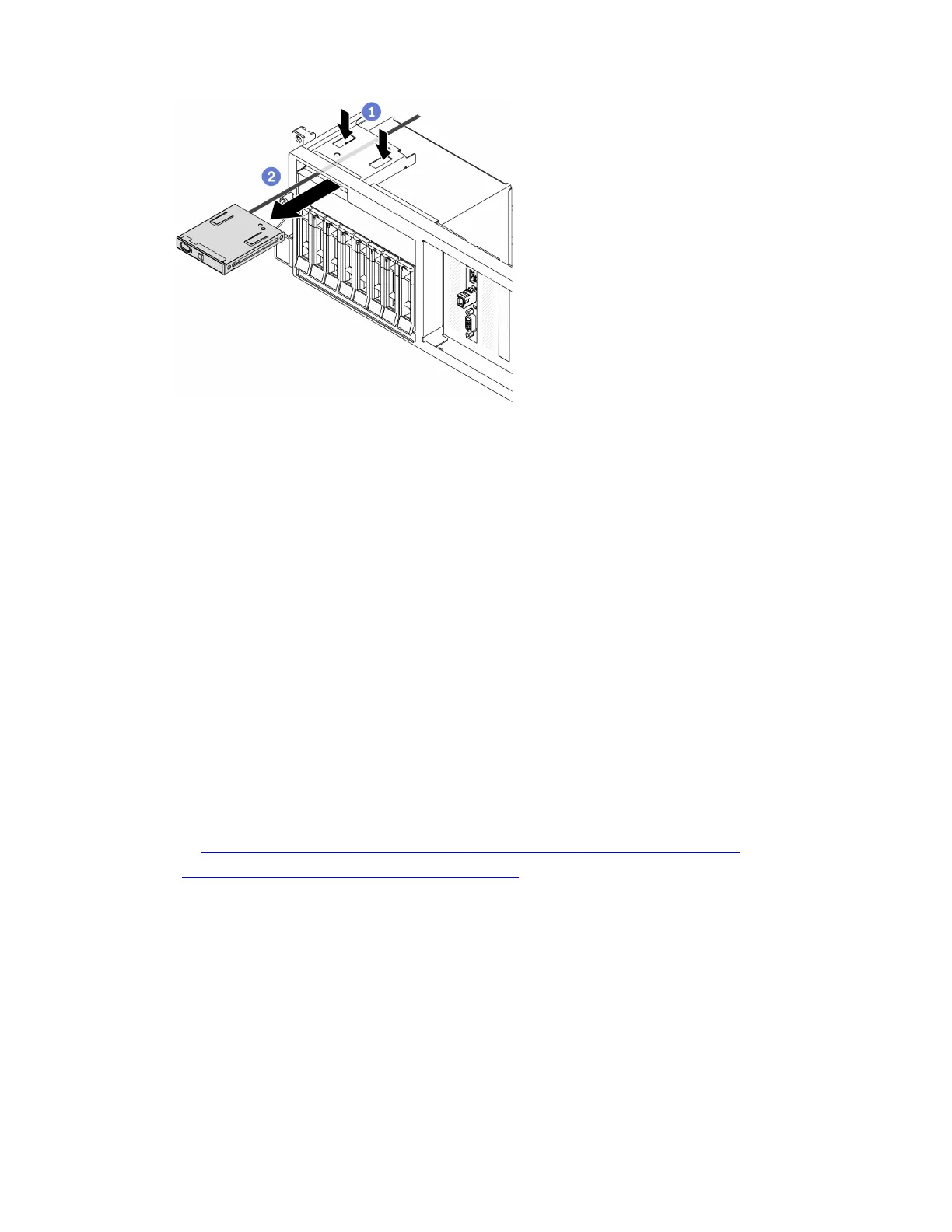
Figure 100. Removing the front panel
After you finish
1. Install a replacement unit. See “Install the front panel” on page 157.
2. If you are instructed to return the component or optional device, follow all packaging instructions, and
use any packaging materials for shipping that are supplied to you.
Install the front panel
Follow instructions in this section to install the front panel.
About this task
Attention:
• Read “Installation Guidelines” on page 121 and “Safety inspection checklist” on page 122 to ensure that
you work safely.
• Touch the static-protective package that contains the component to any unpainted metal surface on the
server; then, remove it from the package and place it on a static-protective surface.
Watch the procedure. A video of the installation and removal process is available:
• YouTube:
https://www.youtube.com/playlist?list=PLYV5R7hVcs-BXei6L6c05osQVLt4w5XYx
• Youku: https://list.youku.com/albumlist/show/id_59636529
Procedure
Step 1. Locate the front panel slot based on the server front view of your configuration. See below for more
details:
• “The 4-DW GPU Model Front view” on page 16
• “The 8-DW GPU Model Front view” on page 18
• “The SXM GPU Model front view” on page 21
Step 2. Align the front panel with the slot on top of the drive bays and slide it in.
Chapter 4. Hardware replacement procedures 157

 Loading...


