• If the server is installed in a rack, slide the server out on its rack slide rails to gain access to the top cover,
or remove the server from the rack. See “Remove the server from rack” on page 124.
Watch the procedure. A video of the installation and removal process is available:
• YouTube:
https://www.youtube.com/playlist?list=PLYV5R7hVcs-BXei6L6c05osQVLt4w5XYx
• Youku: https://list.youku.com/albumlist/show/id_59636529
Procedure
Step 1. Prepare your server.
a. Remove the top cover. See “Remove the top cover” on page 225.
b. Remove all hot-swap drives and drive bay fillers (if any) from the drive bays. See “Remove a
2.5-/3.5-inch hot-swap drive” on page 228. Place the drives on a static protective surface.
c. Disconnect the power and signal cables from the 2.5-inch or 3.5-inch drive backplane.
d. Remove the 2.5-inch or 3.5-inch drive cage assembly. See “Remove the 2.5-/3.5-inch drive
cage assembly” on page 236.
Step 2. Based on your configuration, follow the corresponding procedures to remove the 2.5-inch or 3.5-
inch drive backplane.
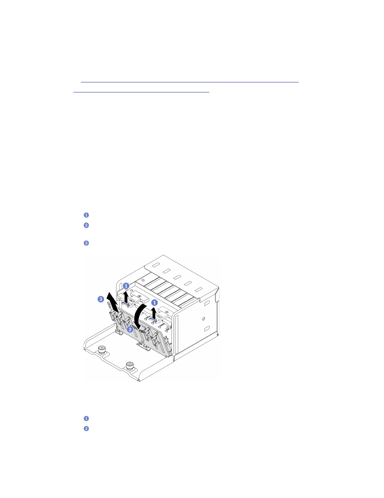
Remove the 2.5-inch drive backplane:
a.
Lift and hold the retention latches on top of the 2.5-inch drive cage.
b.
Rotate the 2.5-inch drive backplane away to disengage it from the retention latches as
illustrated.
c.
Remove the backplane from the drive cage.
Figure 165. Removing the 2.5-inch drive backplane
Remove the 3.5-inch drive backplane:
a.
Pull out the blue plunger that secures the 3.5-inch drive backplane.
b.
Slide the 3.5-inch drive backplane as illustrated to disengage it from the drive cage; then,
remove the backplane from the drive cage.
Chapter 4. Hardware replacement procedures 233

 Loading...


