9300 Servo PLC
Connection
3-31
9300ServoPLC EN 1.4
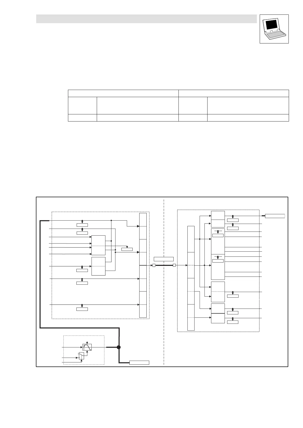
3.4 Application example
The setpoint integrator of drive 1 is to provide the speed setpoint for drives 1 and 2 (see Abb. 3-13).
Settings:
Drive controller 1 Drive controller 2
C0350 = 1 Node = 1;
so that output address for CAN2_OUT = C0350 + 1
=2
C0350 = 2 Node = 2;
so that input address for CAN2_IN = C0350 + 1 =
2
C0352 = 2 Master - -
3.4.1 Programming the application example
This section describes the programming of the application example in Abb. 3-13.
Parameter addressing (code numbers / index)
The parameters for the drive controller are addresssed through the index. The index for Lenze code
numbers (codes) lies in the range from 20567 (5060
hex
) and 24575 (5FFF
hex
)
Conversion formula:
Index = 24575 - Lenze code number
(Relevant entry parameters for the bus system.)
CAN2_OUT
Byte 1,2
Bit 0
Bit 15
Byte 7,8
Byte 5,6
Byte 3,4
CAN2_dnOutD1_p
16 Bit
LowWord
16 Bit
HighWord
16 Bit
LowWord
16 Bit
HighWord
C0869/2
CAN2_nOutW1_a
CAN2_nOutW2_a
C0868/4
C0868/5
CAN2_nOutW3_a
CAN2_nOutW4_a
C0868/6
C0868/7
CAN2_bFDO0_b
CAN2_bFDO15_b
...
CAN2_bFDO16_b
CAN2_bFDO31_b
...
C0151/2
16 Bit
16 Bit
CAN2_nInW1_a
16
binary
signals
16 Bit
LowWord
16 Bit
HighWord
16 Bit
CAN2_nInW3_a
CAN2_bInB0_b
CAN2_dnInD1_p
Byte 3,4
Byte 5,6
Byte 7,8
CAN2_IN
Bit 0
Bit 15
......
C0867/2
C0866/6
C0866/4
C0863/3
C0863/4
C0866/5
Controlword
16 Bit
CAN2_nInW4_a
C0866/7
CAN2_nInW2_a
CAN2_bInB1_b
CAN2_bInB14_b
CAN2_bInB15_b
CAN2_bInB16_b
CAN2_bInB17_b
CAN2_bInB30_b
CAN2_bInB31_b
16
binary
signals
L_RFG
nIn
nOut
dnTir
0
1
nSet
bLoad_b
dnTif
MCTRL_nNSet_a
MCTRL_nNSet_a
X4
X4
A2A1
SYSTEMBUS
Abb. 3-13 Wiring: join X4 of drive controller 1 to X4 of drive controller 2
A1 Drive controller 1
A2 Drive controller 2
 Loading...


