9300 Servo PLC
System blocks
2.1 Introduction
2-3
9300ServoPLC EN 1.4
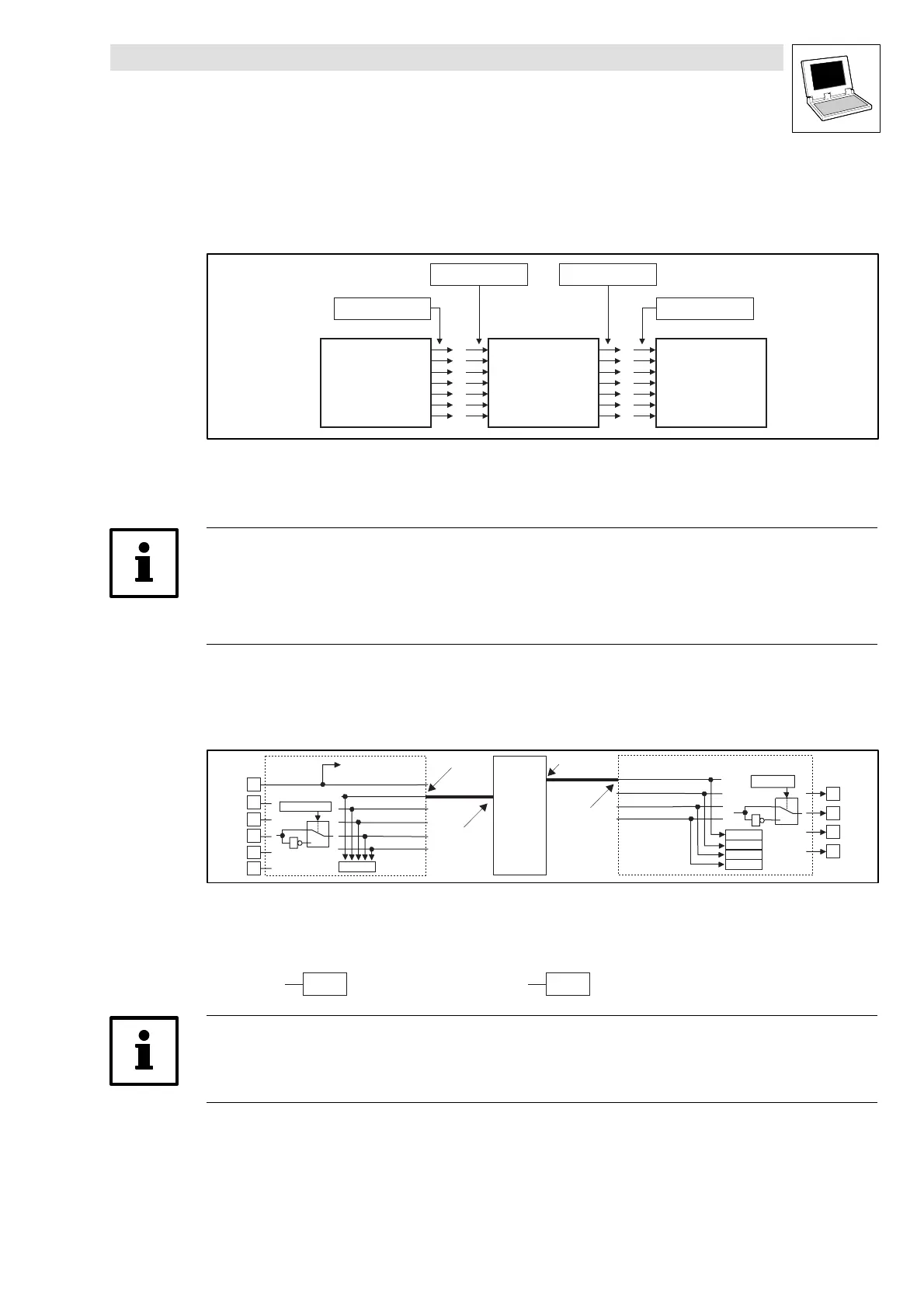
2.1.3 Definition of the system-block inputs/outputs
In order to implement a connection of the user program with thehardware, system blocks arejoined
to program-organisation elements (POEs):
SB
SB-Output
POE-Input POE-Output
SB-Input
SBPOE
Abb. 2-2 Connecting system blocks to a program-organisation element (schematic)
POE Program-organisation element
SB System block
Tip!
The assignments as inputs and outputs are always made from the program viewpoint!
This means that logical system-block outputs are seen by the POEs as hardware-side inputs, and
system-block inputs are seen as outputs.
Example: system block DIGITAL_IO (DIGIN):
For example, to connect the digital input 1 of the PLC run/stop to aPOE,theoutput 1 of the system
block DIGITAL_IO must be connected to an input of the POE:
E1
E2
E3
E4
E5
1
0
C0114/1...5
DIGIN
DIGIN_bIn1_b
DIGIN_bIn2_b
DIGIN_bIn3_b
DIGIN_bIn4_b
DIGIN_bIn5_b
C0443
28
DCTRL -X5/28
X5
DIGIN_bCInh_b
1
A1
A2
A3
A4
1
0
C0118/1...4
DIGOUT
C0444/4
C0444/3
C0444/2
C0444/1
X5
1
DIGOUT_bOut1_b
DIGOUT_bOut2_b
DIGOUT_bOut3_b
DIGOUT_bOut4_b
SB-OUT
SB-IN
POE
POE-IN
POE-OUT
Abb. 2-3 Connecting the system block DIGITAL_IO to a POE
Accesstothedigitalinput1canonlybemadethroughtheabsoluteaddress%IX1.0.1 or through
the system-variable names
DIGIN_bIn1_b
:
POE POE
%IX1.0.1
DIGIN_bIn1_b
Tip!
According to IEC1131, only onecopy of thedigital input can be transferred, and this system variable
must be of type VAR_INPUT
 Loading...


