9300 Servo PLC
Connection
3-10
9300ServoPLC EN 1.4
3.2 System blocks for the system bus
3.2.1 System bus (CAN1_IO)
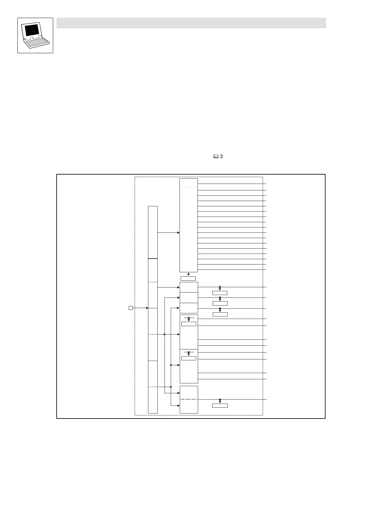
3.2.1.1 Inputs_CAN1 (CAN1_IN)
System bus inputs (Module number: 31)
This SB is used for cyclic data communication with higher-level control systems. A special telegram
(the sync-telegram) must be generated for transmission.
(
^
3-49)
You cannot use this SB for exchanging data between one drive controller and another.
16 Bit
16 Bit
16
binary
signals
16 Bit
LowWord
16 Bit
HighWord
16 Bit
CAN1_nInW1_a
CAN1_bInB0_b
CAN1_dnInD1_p
Byte 3,4
Byte 5,6
Byte 7,8
YSTEMBUS
X4
Bit 0
Bit 15
Controlword
CAN1_bInB14_b
CAN1_bInB2_:b
......
C0867/1
C0866/1
C0866/2
C0863/1
C0863/2
C0866/3
CAN1_nInW2_a
CAN1_nInW3_a
CAN1_bInB15_b
CAN1_bInB16_b
CAN1_bInB17_b
CAN1_bInB30_b
CAN1_bInB31_b
C0136/2
16 Bit
CAN1_wDctrlCtrl
CAN1_bCtrlB0_b
CAN1_bCtrlQuickstop_b
CAN1_bCtrlTripReset_b
CAN1_bCtrlTripSet_b
CAN1_bCtrlCInhibit_b
CAN1_bCtrlDisable_b
CAN1_bCtrlB1_b
CAN1_bCtrlB2_b
CAN1_bCtrlB4_b
CAN1_bCtrlB5_b
CAN1_bCtrlB6_b
CAN1_bCtrlB7_b
CAN1_bCtrlB12_b
CAN1_bCtrlB13_b
CAN1_bCtrlB14_b
CAN1_bCtrlB15_b
CAN1_IN
16
binary
signals
16
binary
signals
Abb. 3-5 Inputs_CAN1 (CAN1_IN)
 Loading...


