9300 Servo PLC
System blocks
2.1 Introduction
2-1
9300ServoPLC EN 1.4
2 System blocks
2.1 Introduction
For a long time, Lenze has followed the principle of describing inverter functions with the aid of
function blocks (FB’s). This principle may also be found in the IEC1131-3 standard.
• The function library includes functions that you can apply as software functions in your
project.
• In addition, quasi-hardware functions are available, as system blocks. (SBs).
System blocks - principle:
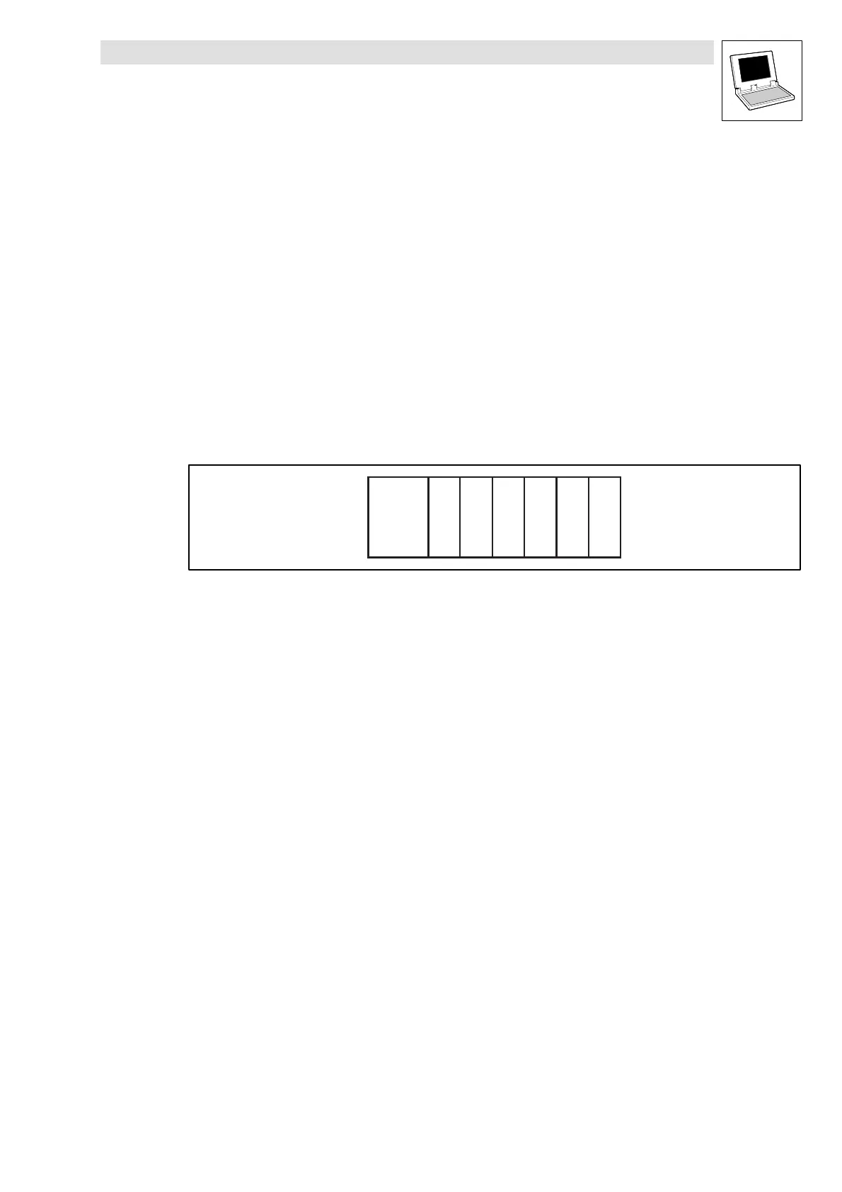
The system-block principle can be explained very well by a PLC system in a rack:
• One element in the rack is the CPU, and next to it there can also be found digital I/Os, analog
I/Os, counter cards, positioning cards etc.
CPU
xxxxxx
Abb. 2-1 Principle of a PLC system (x = expansion cards)
• The CPU can access the inserted cards directly, and process the resulting information.
• The individual expansion cards each have a fixed address for access.
With the Lenze Automation System, the system blocks correspond to these inserted cards!
System blocksarethus special (quasi-hardware)function blocksthat arepermanently integrated into
the run-time system (e.g. 9300 Servo PLC, Drive PLC).
• These function blocks can also partially address real hardware.
• The assignment/identification of the system blocks is made through module numbers.
• The access to the inputs/outputs of the system blocks is made directly through I/O-variables
or fixed memory addresses.
Example:
On example of a system block is the digital I/O-function block “DIGITAL_IO”.
• Accesstothedigitalinput1ofthisSBcanbemadethroughtheabsoluteaddress
(e.g. %IX1.0.1) or via the corresponding I/O-variable (
DIGIN_bIn1_b
).
 Loading...


