Chapter 8- Operating Instructions Liebert Hipulse E User Manual
Single or '1+N' UPS System Operator Control and Display Panel
Page 8-8 (07/04)
LCD Display Panel Messages
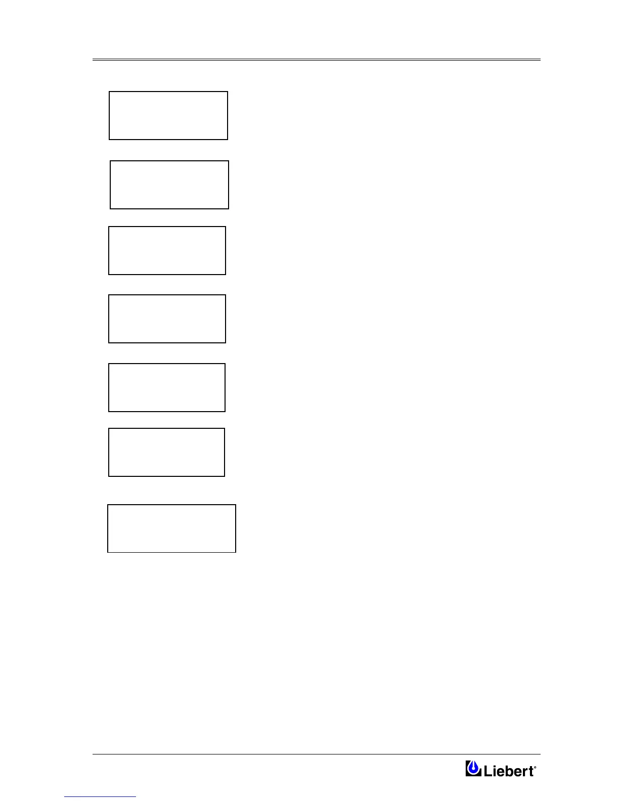
• Initializing Window.
After first connecting power to the UPS and closing the bypass a.c.
input power switch, the INITIALIZATION message will appear on the
LCD screen. It persists for about five seconds while the control
firmware is loaded and the unit performs a self test. It is followed by a
window showing various messages with the time and date on the bottom
line.
When the power switches and battery circuit breaker have been closed
and the inverter has stabilized the window will change to the default
window.
• Default Window.
The message shown below, will be seen on the default window
whenever the UPS is operating normally:
The top lines display the UPS operational status and indicates alarm
conditions when they occur; and line four normally shows the time and
date.
If the ECOMODE configuration is in effect, the default window will be
modified as shown to the side.
• Info Window.
From Default Window, pressing the ESC key, information about the
modem programmed in memory and its connection are shown on
display.
Pressing again the ESC key, software release are shown, both on UPS
board and on Panel board: this feature is useful upgrading SW for next
versions and to know exactly features of present release.
Pressing again ESC key it goes back to Default Window.
• Main Menu Window.
The main menu is selected from the Default Window by pressing the
ENTER key:
The four windows accessed from the Main Menu offer further options
which are described in the relevant chapters of this manual.
The MEASUREMENT option gives access to windows which show the
present values of parameters such as input & output voltages and
current, load etc. These parameters are useful when determining the
state of the UPS or the causes of alarms, and are described in more
detail below.
The ALARM HISTORY window displays detailed current and
historical event, warnings and alarm can be scrolled on the UPS display
or can be simultaneously gathered through background RS232 port or
LAN. The ALARM HISTORY procedure is detailed in Chapter 9.
LIEBERT
UPS
RECTIF. SWITCH OPEN
BATTERY C.B. OPEN
OUTPUT SWITCH OPEN
HH.MM.SS DD.MM.YY
NORMAL OPERATION
HH.MM.SS DD.MM.YY
>MEASUR./ALARM HIST.<
FUNCTION
MAINTENANCE
SETUP
SW VERSION
PANEL V xx.x
UPS LOGIC V xx.x
MODEM TYPE 3COM
U.S.ROBOTICS
MODEM STATUS:
NOT CONNECTED
NORMAL OPERATION
(ECOMODE)
HH.MM.SS DD.MM.YY