Do you have a question about the LNC T6 Series and is the answer not in the manual?
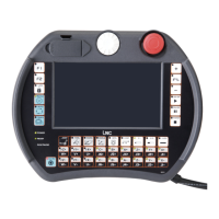
Describes LCD MONITOR and MDIOP units of control panels.
Explains Main, Sub-Function, and Additional function keys on the LCD screen.
Introduces 8 function groups and details screen layout elements.
Details the numbered elements of the CNC display screen for user reference.
Describes the coordinate display screen and its selectable views like ABS, REL, MAC.
Details file operations: opening, copying, deleting, renaming, and setting menus.
Explains automatic program checking and available options like SINGLE CHECK.
Describes entering the MDI page to execute single block programs or multi-line MDI.
Covers receiving and transmitting programs between controller and PCs via RS232.
Details how to input tool wear data under MDI mode, with 30 settings available.
Explains entering the GEOM screen to modify outline offsets with 30 types of settings.
Describes entering the work shift setting screen and methods for key-in values.
Guides users to the MACRO variable screen for local and common variables.
Explains entering the working coordinate setting screen for systems like G54-G59.
Introduces automated working path program generation using 14 working methods.
Details steps for creating a working path program: project file, method selection, tool input, etc.
Explains the Main Function screen layout, column descriptions, and function keys.
Describes entering the GRAPH group to view working paths and set display ranges.
Details the path display screen, absolute coordinates, and view angle settings.
Explains the SET screen for defining coordinate view angles and drawing surface parameters.
Describes the ALARM screen for viewing and resolving system problems, including WARN, HISMSG, LOGHST.
Explains checking I/O and system internal conditions, including I, O, C, S, A statuses.
Covers the MLC2 screen with functions like LAD, CNT, REG, DRG, and TMR for ladder logic and data viewing.
Displays system maintenance variables for designers and technicians, including H.D. checks.
Details hardware diagnosis checks for connection cables and jump positions, indicating errors with 'X'.
Shows cutting time, run time, and working piece count, with buttons to clear these values.
Allows system updates like SYSUND, disk diagnosis, and parameter backup/restore when CNC is not ready.
Introduces parameter settings and modification via NC.SYS, with user levels and password input.
Details the USROPT page with 40 sets of parameters for user-specific options.
Allows checking and setting time limits for system usage, potentially locking features.
Covers network settings for connecting the controller to a PC, including NET and ReCON methods.
Explains how to change user passwords for parameter modification, distinguishing End-User and Machine Maker roles.
Describes switching between End-User and Machine Maker identities, each with different parameter access.
Lists and describes the 11 main functions of the operation panel.
Explains the meaning of various LED indicators like ALARM, READY, and axis ZRN status.
Details axis movement commands for JOG and ZRN modes using directional keys.
Lists and describes the 7 operational modes: EDIT, MEM, MDI, MPG, ZRN, JOG, RAPID.
Explains spindle operation buttons (CW, STOP, CCW) and speed adjustment via UP/DOWN buttons.
Introduces optional function buttons like SBK, OP STOP, AUTO, COOL for enhanced operation.
Describes the emergency stop button function, which halts all motions and sets the system to "Not Ready".
Explains the CYCLE START button for program execution and FEED HOLD for temporary program pausing.
Details the button for adjusting feedrate/rapid rate from 0% to 150% during program execution.
Covers locking program edit mode and displaying tool numbers during calling or switching.
Explains the functions of the POWER ON and POWER OFF buttons for the CNC controller.
Outlines hardware requirements and connection specifications for RS232 communication.
Provides step-by-step instructions for installing the LNC ReCON 232 software on the PC.
Details the necessary RS232 settings on the NC end to match PC settings for successful communication.
Introduces DNC functions for transferring files between PC and NC, detailing upload/download processes.
Guides on uploading and saving path programs using ReCON software from controller to PC.
Details steps for uploading and saving path programs using ReCON software from controller to PC.
Explains the process for uploading and saving path programs using general software via PC and NC.
Provides guidance on using USB to RS232 transfer, including device manager settings and driver installation.
| Input Voltage | 12-24V DC |
|---|---|
| Operating Temperature | -20°C to +60°C |
| Storage Temperature | -40°C to +85°C |
| Protection | Overload, Short Circuit, Over Temperature |
| Output Current | 6A |