7528%/(6+227,1* 9HUVD3XOVHPowerSuite6HULHV6HUYLFH0DQXDO
5(9%
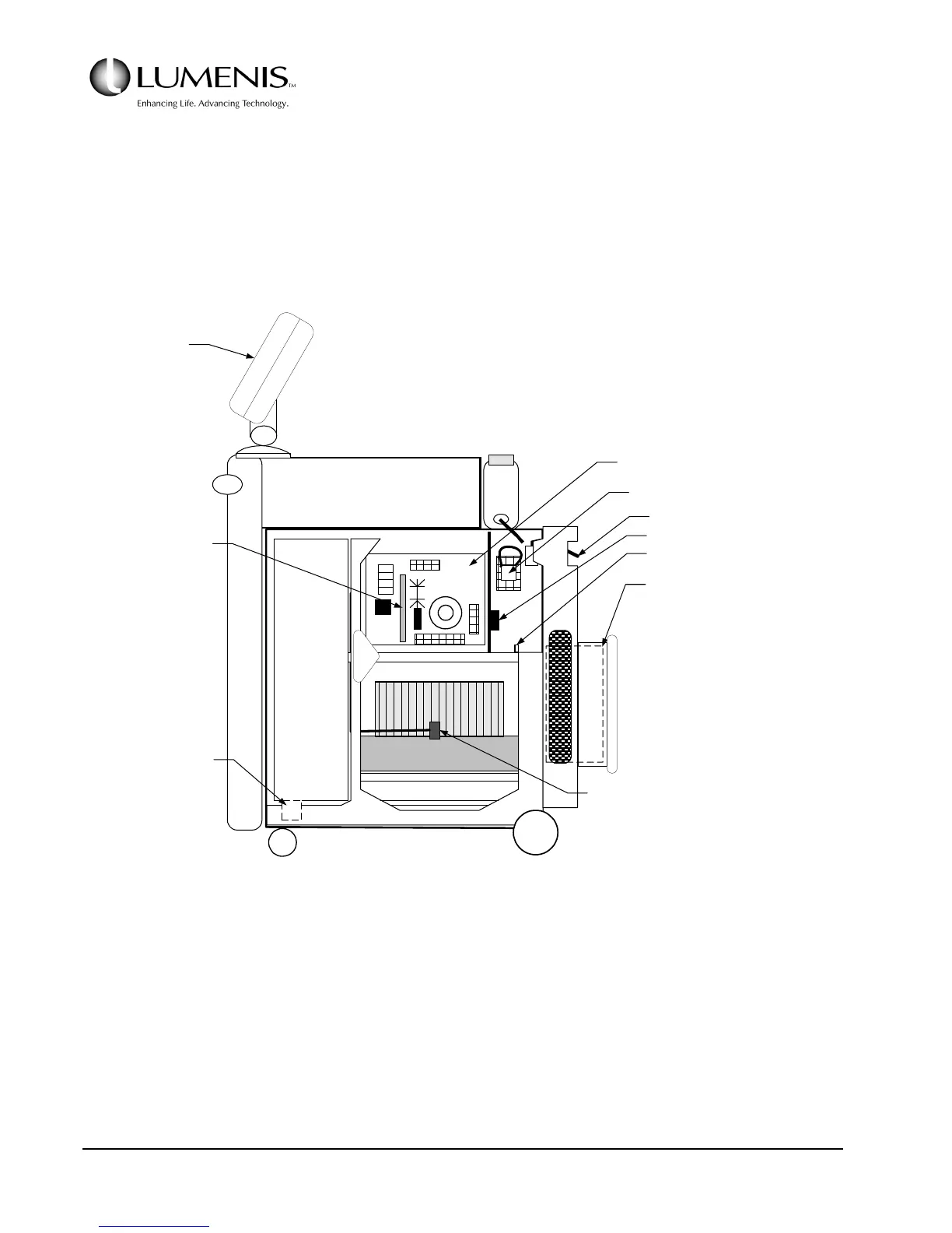
Remove the right side cover to access the fuses, AC Control PCB, main contactor, the circuit breaker, HVPS,
Tachometer PCB, and to access the interior of the enclosure
To remove the right side cover, open the front cover, remove the top cover, remove the single screw that
secures the cover at the bottom just in front of the rear wheel, then remove the six screws along the top and
front of the cover (three along the top, three along the front). The cover can then be lifted off of the frame.
FIG. 5.10: INTERIOR VIEW, RIGHT SIDE
FUSES
HEAT EXCHANGER
MAIN
RESERVOIR
COOLING FAN
HVPS
FILL RES.
OPTICS BENCH
BACK
TACHOMETER PCB
FAN SPEED
CONTROLLER
AC CONTROL PCB
(Refer to Fig. A*)
CIRCUIT BREAKER
MAIN & AUX. CONTACTOR
TERMINAL BLOCK
CHASSIS GROUNDING POST
ISOLATION TRANSFORMER
(Behind the rear cover)
AIR TEMP
SENSOR
(FAN)
LCD
DISPLAY