&$/$'-867$/,*1 9HUVD3XOVH3RZHU6XLWH6HULHV6HUYLFH0DQXDO
5(9%
3.2.6 Aiming Beam Alignment
The aiming beam can be adjusted by repositioning the aiming diode mount or by adjusting the position of the
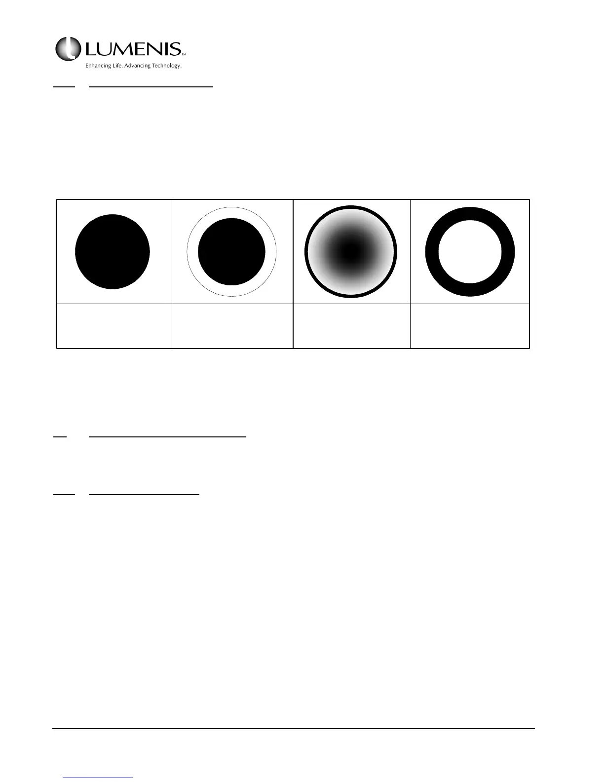
folding mirror (the mirror that directs the aiming beam onto the beam combiner). Observe the aiming beam
output from the fiber and adjust to obtain a full spot of bright red light (no doughnut). Note: A faint halo is
acceptable. Refer to Fig. 3.8.
FIG. 3.8: AIMING BEAM PROFILE
3.3 ELECTRICAL ADJUSTMENTS
3.3.1 Voltage Configuration
The VersaPulse Select PowerSuite can be configured to operate with the AC mains voltage at 220VAC ±10% by
setting various jumpers on the AC Control PCB. Refer to Figure 3.9 and the procedure below in configuring
the AC Control PCB.
1. Set up
a. Measure the AC mains voltage and record on the Certification Report.
b. Verify the VersaPulse PowerSuite is not connected to the AC mains.
c. Open the front door and remove the right side cover. (Refer to Section 5).
ACCEPTABLE ACCEPTABLE UNACCEPTABLE UNACCEPTABLE
(Ideal) (Faint Halo) (Bright Halo) (Aiming Beam
is out of Alignment)