9HUVD3XOVH3RZHU6XLWH6HULHV6HUYLFH0DQXDO &$/$'-867$/,*1
5(9%
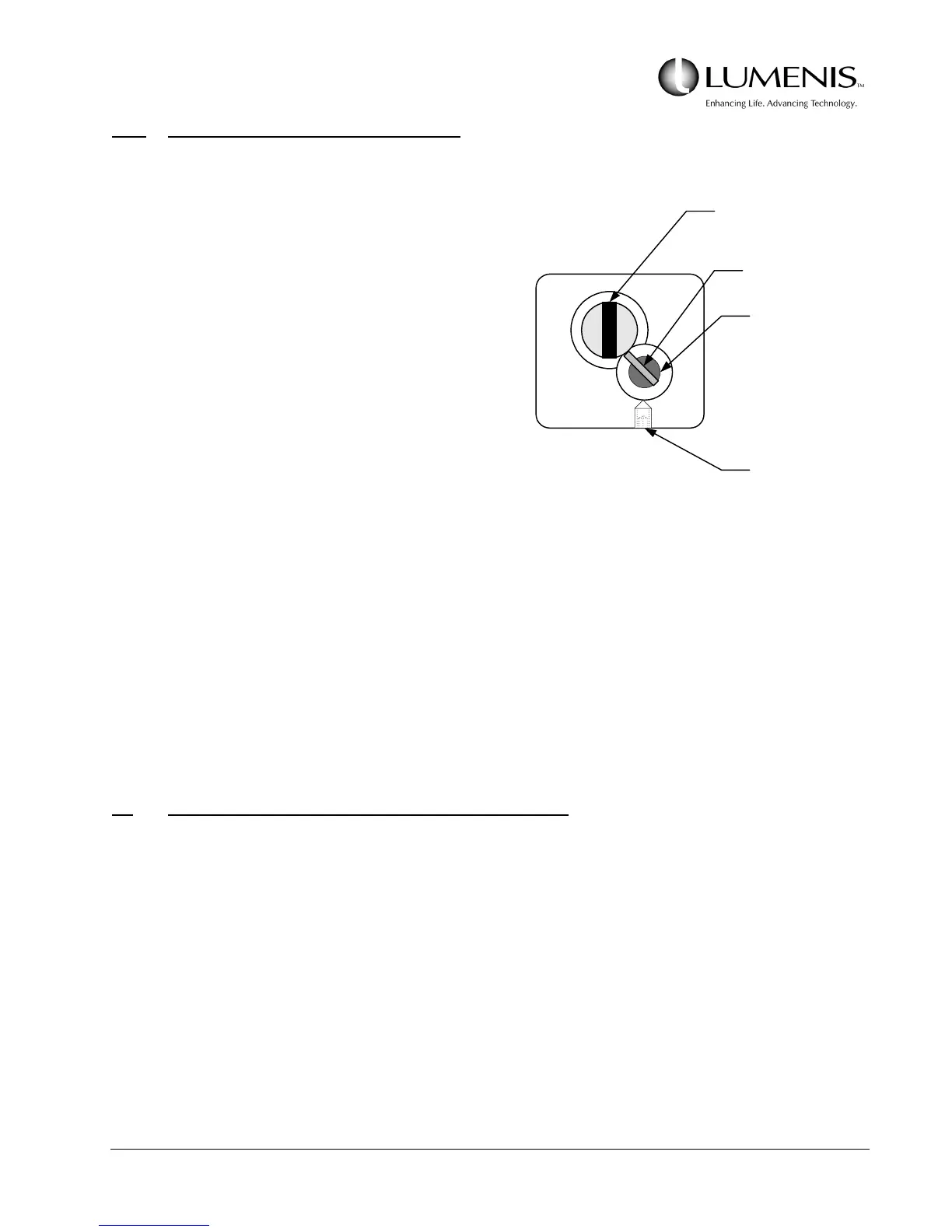
3.4.2 Blastshield Sense Switch Adjustment
Perform this procedure if the blast shield has been inserted
and the INSERT DEBRIS SHIELD message remains ON.
Refer to Fig. 3.11.
1. Open the front door and remove the blastshield access
door from the front door; locate LED11 on the Control-
ler PCB or connect a DVM across TP50 (BLST) and
TP46 (GND).
2. Reach around the right side of the laser head casting
and locate the blastshield; remove the blastshield.
3. Adjust the blastshield switch.
The blastshield switch is located behind the blast-
shield alignment pin. Loosen the set screw securing
the blastshield sensing switch and adjust the switch so that LED11 comes ON or TP50 goes HIGH on
the DVM just before the blastshield is fully seated in the detent.
a. If LED11 comes ON with more than 2mm of travel before the blastshield snaps into the detent,
loosen the set screw and slightly push the blastshield switch IN to the casting and recheck.
b. If LED 11 does not come ON or intermittently comes ON when in the detent position, loosen the set
screw and pull the blastshield switch OUT of the laser head casting and recheck.
3.5 ENERGY MONITOR AND AUTO CALIBRATION
The energy monitor calibration procedure adjusts energy monitor amplifier circuit gains to establish a
conversion factor in terms of Volts/Joule by referencing delivered Holmium and Nd:YAG laser energy as
measured on a calibrated external power meter. The optical calibration procedure determines optical
transmission characteristics of an intra-beam attenuator optic for Holmium wavelength (Ho & Nd of a dual
wavelength system) and if the laser is a dual wavelength system, the procedure determines the reflectivity
characteristics of the pick-off mirrors for the Neodymium wavelength. Then at each system turn-on cycle, the
software executes an automatic laser calibration (autocal) which allows the computer to determine and store
(in NVRAM) the flashlamp drive parameters required to generate minimum and maximum pulse energies for
each installed laser channel.
NOTE: All Laser Safety procedures must be followed while performing this procedure (i.e., safety
glasses/goggles must be worn).
Blastshield
Alignment Pin
Blastshield
Assembly
Blastshield
Sense Switch
Blastshield
Sense Switch
set screw
FIG. 3.11: BLASTSHIELD SENSE SWITCH