,167$//$7,21 9HUVD3XOVH3RZHU6XLWH6HULHV6HUYLFH0DQXDO
5(9%
b. Verify the VersaPulse PowerSuite is not connected to the AC mains.
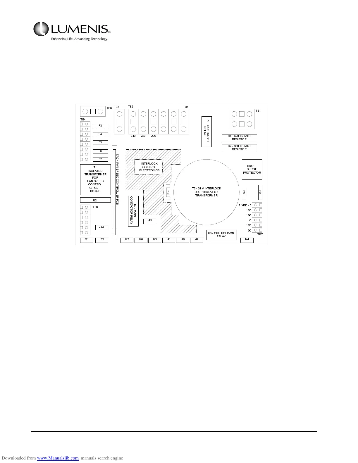
2. Locate the AC Control PCB (behind the right side panel) and identify TB5 & TB2 (top of the PCB).
Refer to Fig. 2.2.
FIG. 2.2 AC CONTROL PCB
3. Locate the large brown wire in TB5-1 and position the other end in TB2 as follows:
a. For mains voltage in 190 - 210 VAC range, connect TB5-1 to TB2-2.
b. For mains voltage in 211 - 230 VAC range, connect TB5-1 to TB2-3.
c. For mains voltage in 231 - 264 VAC range, connect TB5-1 to TB2-4.
4. Locate the two small blue jumper wires in TB7 (bottom right). Position the jumpers as follows:
a. For mains voltage in 190 - 210 VAC range, jumper TB7: 1-3, 4-6.
b. For mains voltage in 211 - 230 VAC range, jumper TB7: 1-3, 5-6.
)
)
)
)
)
.
6
2
)
7
6
7
$
5
7
5
(
/
$
<
562)767$57
5(6,6725
562)767$57
5(6,6725
65*
685*(
3527(&725
)
)
)
79,17(5/2&.
/223,62/$7,21
75$16)250(5
7
,62/$7('
75$16)250(5
)25
)$163(('
&21752/
&,5&8,7
%2$5'
8
7%
7%
7%
7%
7%
7%
7%
7%
7
$
&
+
)
$
1
6
3
(
(
'
&
2
1
7
5
2
/
/
(
5
3
&
%
.
0
$
,
1
&
2
1
7
$
&
7
2
5
5
(
/
$
<
.&38+2/'21
5(/$<
-
-- - - - - - -
-
-
),;('
,17(5/2&.
&21752/
(/(&7521,&6