9HUVD3XOVH3RZHU6XLWH6HULHV6HUYLFH0DQXDO &$/$'-867$/,*1
5(9%
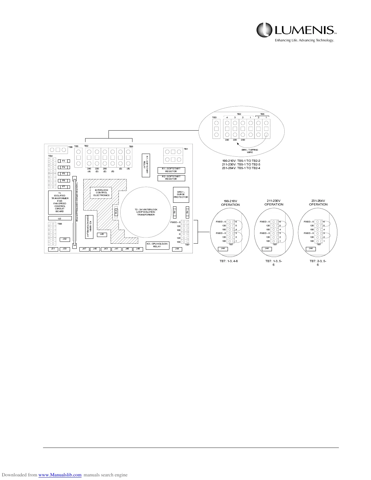
2. Locate the AC Control PCB (behind the right side panel) and identify TB5 & TB2 (top of the AC Control
PCB). Refer to Fig. 3.9.
3. Locate the large brown wire in TB5-1 and position the other end in TB2 as follows in Fig. 3.9:
FIG. 3.9: AC CONFIGURATION ON THE AC CONTROL PCB
4. Locate the two small blue jumper wires in TB7 (bottom right). Position the jumpers as illustrated in
Fig. 3.9.
5. Connect to system to the AC service.
CAUTION: Once connected to the site electrical service, lethal voltages are present inside the unit.
The AC power is present at the circuit breaker, main contactor and isolation transformer. In addition,
the isolation transformer secondary outputs are “hot”. Review and understand the safety subtopic in
Section 5 before preceeding.
The system can be hard wired to electrical service, but ismore typically connected by a plug to an elec-
trical outlet.
7%
7% 7%
%517$33,1*
:,5(
97%727%
97%727%
97%727%
)
)
)
)
)
.
6
2
)
7
6
7
$
5
7
5
(
/
$
<
562)767$57
5(6,6725
562)767$57
5(6,6725
65*
685*(
3527(&725
)
)
)
79,17(5/2&.
/223,62/$7,21
75$16)250(5
7
,62/$7('
75$16)250(5
)25
)$163(('
&21752/
&,5&8,7
%2$5'
8
7%
7%
7%
7%
7%
7%
7%
7%
7
$
&
+
)
$
1
6
3
(
(
'
&
2
1
7
5
2
/
/
(
5
3
&
%
.
0
$
,
1
&
2
1
7
$
&
7
2
5
5
(
/
$
<
.&38+2/'21
5(/$<
-
-- - - - - - -
-
-
),;('
,17(5/2&.
&21752/
(/(&7521,&6
7%
-
),;('
),;('
9
23(5$7,21
7%
7%
-
),;('
),;('
9
23(5$7,21
7%
7%
-
),;('
),;('
9
23(5$7,21
7%